5 connecting the cables in the sunny central, Connecting the cables in the sunny central, Connection to terminals – SMA VOLTAGE STABILIZER User Manual
Page 20
5 Electrical Connection
SMA Solar Technology AG
20
Ukonstanter-IEN103610
Installation Guide
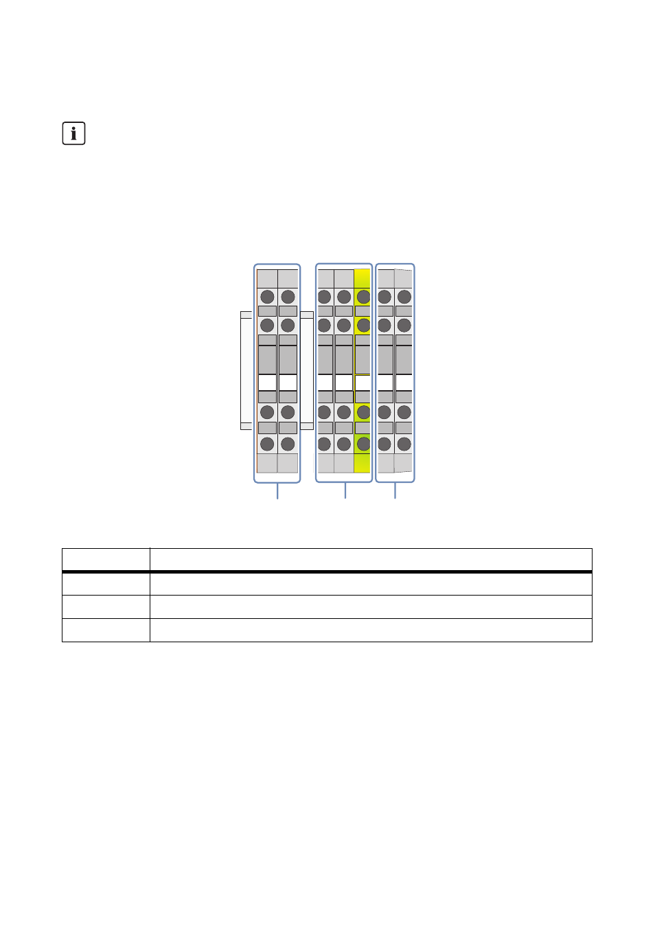
5.5 Connecting the Cables in the Sunny Central
Overview of the Connection Area in the Sunny Central
Figure 10: Connection terminal strip in the Sunny Central, examples shown here are for options 2/0 and 5/5
Connection to Terminals
• All connection terminals that are not being used must be screwed tightly.
• Strip 5 mm from the cable insulation.
• Observe the following torques when connecting the cables to the terminals:
Circuit Diagram
For all electrical connections, it is imperative that you use the provided Sunny Central circuit
diagram. The exact position of the terminal strip can be determined with the help of the
reference designation.
Object
Description
A
Temperature monitoring
B
230 V circuit
C
415 V circuit
M3
0.6 … 0.8 Nm
M4
1.5 … 1.8 Nm
M6
3.2 … 3.7 Nm
5
4
3
2
1
2
1
A
C
B
Z120
-X
120
Z121
-X
121
- SUNNY PORTAL (75 pages)
- SB 2.5-1VL-40 (60 pages)
- SB 2.5-1VL-40 Service Manual (36 pages)
- SB 240 (78 pages)
- FLX Pro 17 (12 pages)
- FLX Series GSM Option Kit (48 pages)
- FLX Series Sensor Interface Option (51 pages)
- FLX Series PLA Option (62 pages)
- FLX Series (248 pages)
- 25000TL (52 pages)
- 25000TL Installation (40 pages)
- 25000TL Service Manual (46 pages)
- CBL-DC-CMB8-10 (24 pages)
- 25000TL Quick Installation Guide (36 pages)
- STP 60-10 Replacing a Defective Fan (12 pages)
- STP 60-10 Replacing Defective Surge Arresters (12 pages)
- Webconnect Systems in SUNNY PORTAL (69 pages)
- STP 12000TL (68 pages)
- STP 60-US-10 Installation (232 pages)
- 485 Data Module Type B (24 pages)
- STP 12000TL Quick Installation Guide (28 pages)
- 1000-US (52 pages)
- STP 24000TL-US (78 pages)
- STP 17000TL (60 pages)
- STP 20000TL (2 pages)
- SB 6000TL Service Manual (46 pages)
- MULTIFUNCTION RELAY (32 pages)
- SB 5000TL (60 pages)
- SB 5000TL Quick Installation Guide (32 pages)
- FANKIT01-10 (24 pages)
- SB 7700TL-US (28 pages)
- FANKIT02-10 (24 pages)
- SB 7700TL-US Installation (96 pages)
- SUNNY MINI CENTRAL (48 pages)
- DC Disconnect Switch For SB 3800-U (32 pages)
- SB 4000-US (100 pages)
- DB-DC-DISCON (4 pages)
- SB 3800-U (86 pages)
- POWER BALANCER (28 pages)
- SB 8000-US (104 pages)
- SB 11000TL‑US (40 pages)
- SMC 11000TL (24 pages)
- SBCBTL6 (36 pages)
- SB 11000TL‑US Installation (92 pages)
- SMC 11000TL Installation (96 pages)