2 overview of the connection area, 1 view from below, Overview of the connection area – SMA SB 1300TL User Manual
Page 22: View from below
6.2
Overview of the Connection Area
6.2.1
View from Below
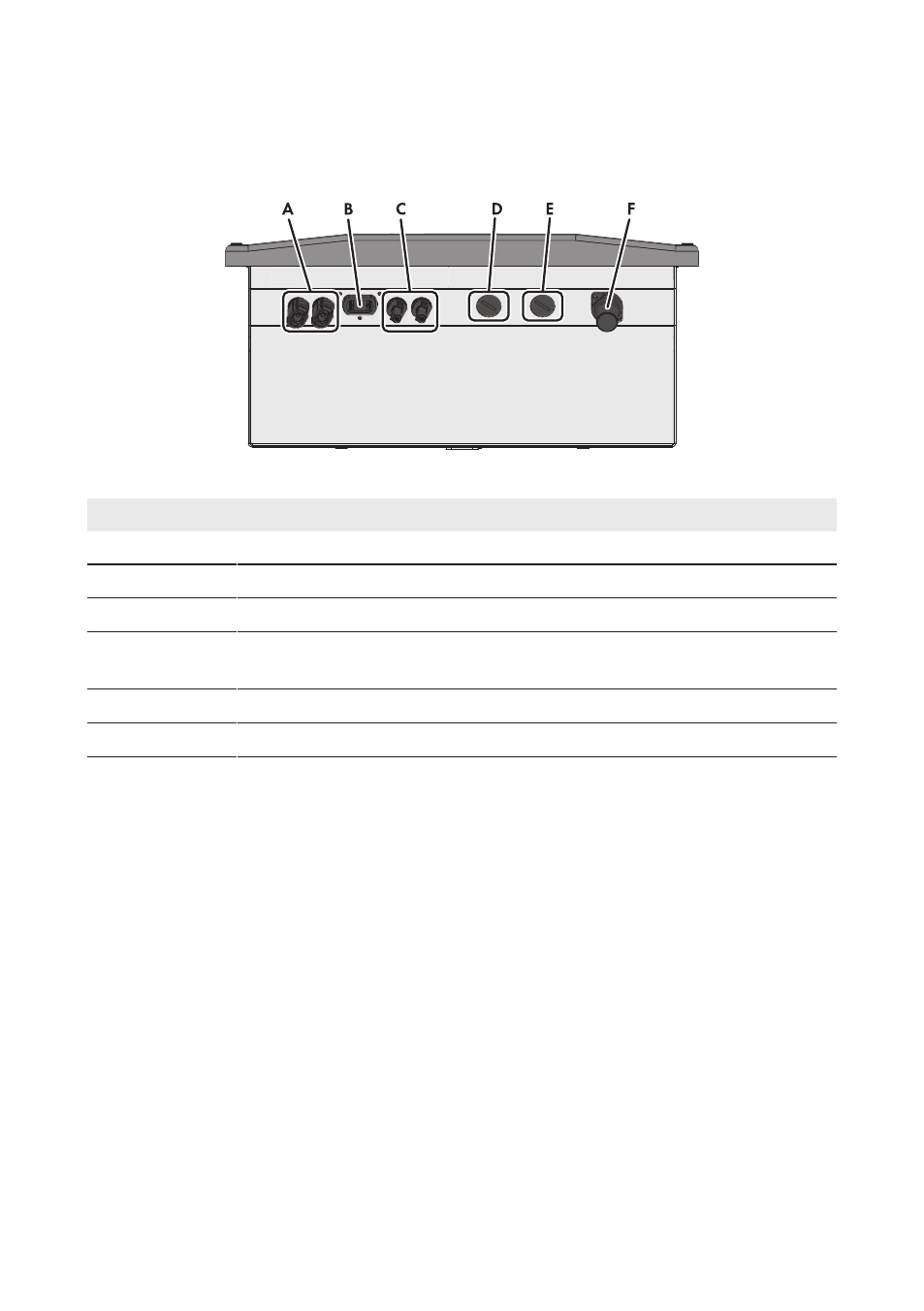
Figure 6: Connection areas and enclosure openings at the bottom of the inverter
Position
Designation
A
Positive DC connector*
B
Pin connector for the ESS**
C
Negative DC connector*
D
Enclosure opening with filler plug for the connection cable of the multifunction
relay
E
Enclosure opening with filler plug for the data cables or network cables
E
Pin connector for the AC connection socket
* As standard, SB 1300TL and SB 1600TL-10 are equipped with a positive and a negative DC connector
** Optional
6 Electrical Connection
SMA Solar Technology AG
Operating Manual
SB13-21TL-BE-en-11
22