2 connecting the antenna cable to the radio module, 3 cabling the inverters, Connecting the antenna cable to the radio module – SMA Wireless-Set485-01 User Manual
Page 17: Cabling the inverters
SMA Solar Technology AG
Electrical Connection
Installation Guide
WirelessSet485-IEN091511
17
We recommend the following cable types for the outdoors:
• SMA communication cable: COMCAB-OUTxxx*
* available in lengths xxx=100 m/200 m/500 m and 1000 m.
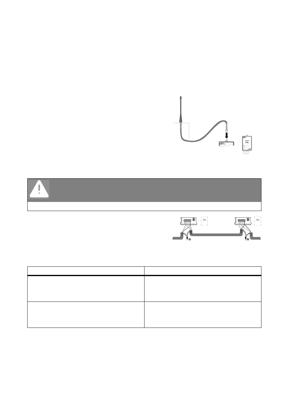
5.2 Connecting the Antenna Cable to the Radio Module
Screw the antenna cable hand-tight onto the radio
module.
You have successfully mounted the antenna.
5.3 Cabling the Inverters
1. Cabling of inverters must always be carried out in
accordance with the specific instructions for each
inverter model. The connection procedure is
described in the corresponding piggyback or
module manual.
2. Establish termination on the inverter:
3. Close the inverter as described in the inverter manual.
The inverters are now wired up.
DANGER!
Risk of lethal electric shock when working on the inverter.
• Open the inverter as described in the inverter manual.
If...
Then...
The inverter is at the center of the RS485
communication bus
- Do not establish termination (jumper A).
- Do not establish pull-up/pull-down of signal
(jumpers B and C).
Inverter at the end of the RS485 communication
bus
- Establish termination (jumper A)
- Do not establish pull-up/pull-down of signal
(jumpers B and C).