ShoreLand'r SL30BAL User Manual
Page 4
Midwest Industries, Inc.
Ida Grove, IA 51445
(800)859-3028
www.shorelandr.com
M301237
REV A 9/18/03
Page 4
Tire Size: ST215/75R 14-C
GVWR: 3740 lb.
Carrying Capacity: 3000 lbs.
Axle: Brake
Refer to the tire side wall for correct tire pressure.
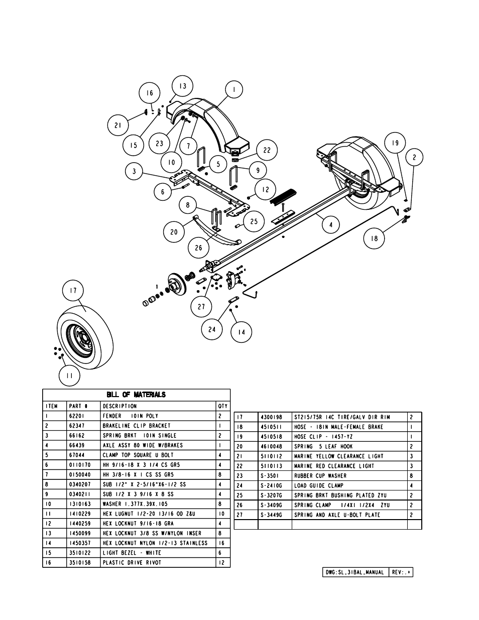
Springs
Position the axle so that it is aligned with the trailer.
Position the brake axle so that the disc brake
calipers are on the back side of the axle.
Place the springs on the topside of the spring pads
welded to the axle. (See chassis diagram) The hook end
of the spring must be mounted to the rear of the trailer.
Place a spring clamp on the top center of the spring.
Place the 1/2” x 6-1/2” U-bolts over the top of the spring
clamp, spring and axle. Place the spring and axle U-bolt
plate onto the ends of the two U-bolts. Secure in place
with 1/2” lock nuts. Tighten.
Axle
Place a spring bracket bushing (Ref #25) into the rear
of the spring bracket and secure with a 9/16” x 3 1/4”
hex bolt and hex lock nut. Repeat in other spring
bracket. Position the axle under the frame, hook the
hook loop of the spring around the bushings just in-
stalled. Note: If the axle is positioned too low, the hooks
will not hook around the bushings.
Raise the front of the springs up so they align with the
front hole of the spring bracket. Secure in place with
9/16” x 3-1/4” hex bolts and lock nuts.
Tighten all axle U-bolts and spring bolts.