HEIDENHAIN TNC 320 (340 55x-05) User Manual
Page 352
352
Programming: Multiple Axis Machining
1
1
.2 The PLANE F
unction: Tilting the W
o
rk
ing Plane (Sof
tw
ar
e Option 1)
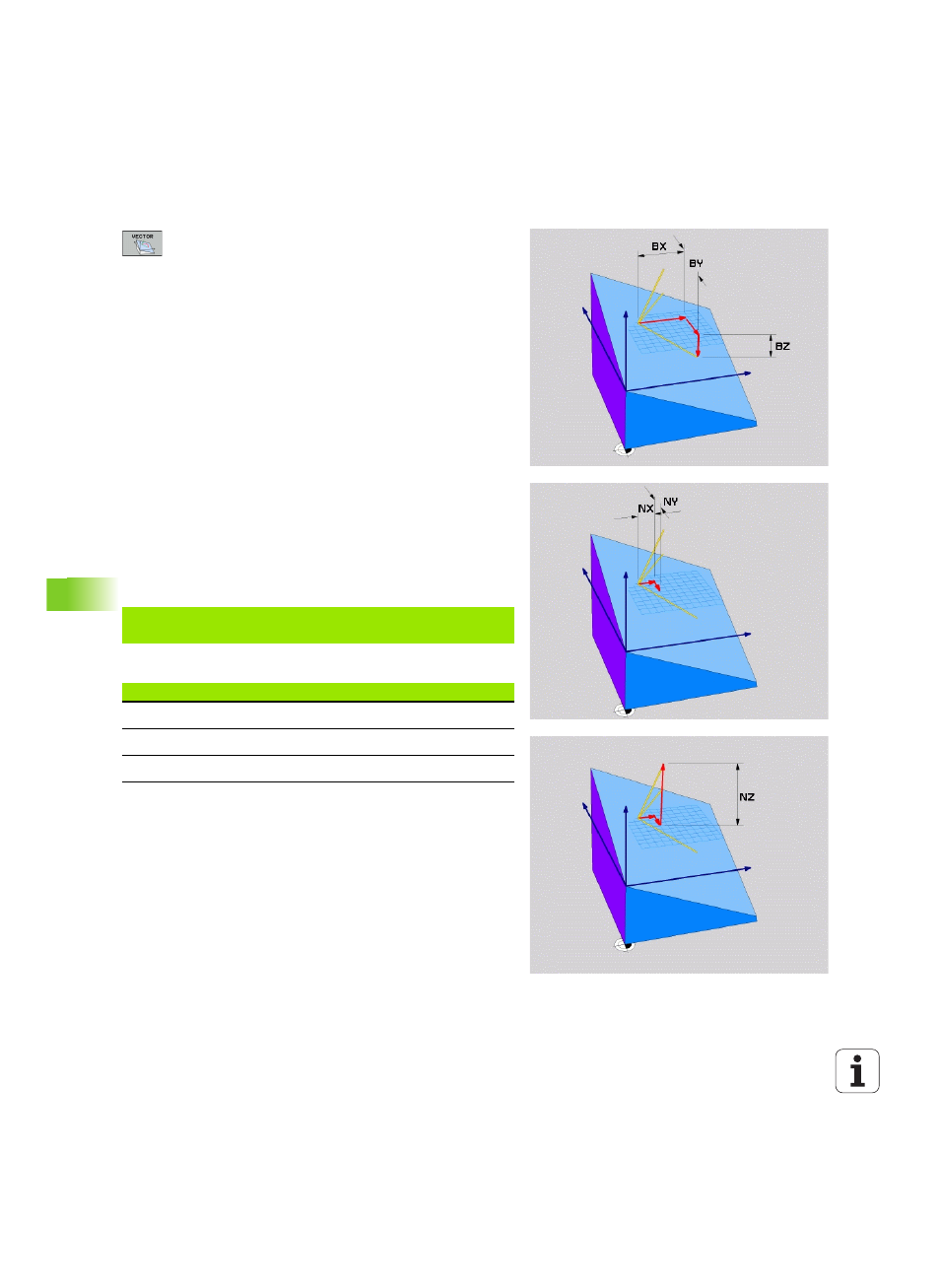
Input parameters
U
X component of base vector?:
X component BX of
the base vector B (see figure at top right). Input
range: –9.9999999 to +9.9999999
U
Y component of base vector?:
Y component BY of
the base vector B (see figure at top right). Input
range: –9.9999999 to +9.9999999
U
Z component of base vector?:
Z component BZ of
the base vector B (see figure at top right). Input
range: –9.9999999 to +9.9999999
U
X component of normal vector?:
X component NX of
the normal vector N (see figure at center right). Input
range: –9.9999999 to +9.9999999
U
Y component of normal vector?:
Y component NY of
the normal vector N (see figure at center right). Input
range: –9.9999999 to +9.9999999
U
Z component of normal vector?:
Z component NZ of
the normal vector N (see figure at lower right). Input
range: –9.9999999 to +9.9999999
U
Continue with the positioning properties (see
"Specifying the positioning behavior of the PLANE
function" on page 358)
NC block
Abbreviations used
5 PLANE VECTOR BX0.8 BY-0.4 BZ-
0.4472 NX0.2 NY0.2 NZ0.9592 ...
Abbreviation
Meaning
VECTOR
Vector
BX, BY, BZ
Base vector: X, Y and Z components
NX, NY, NZ
Normal vector: X, Y and Z components