Measured value output – HEIDENHAIN ND 920 User Manual
Page 58
58
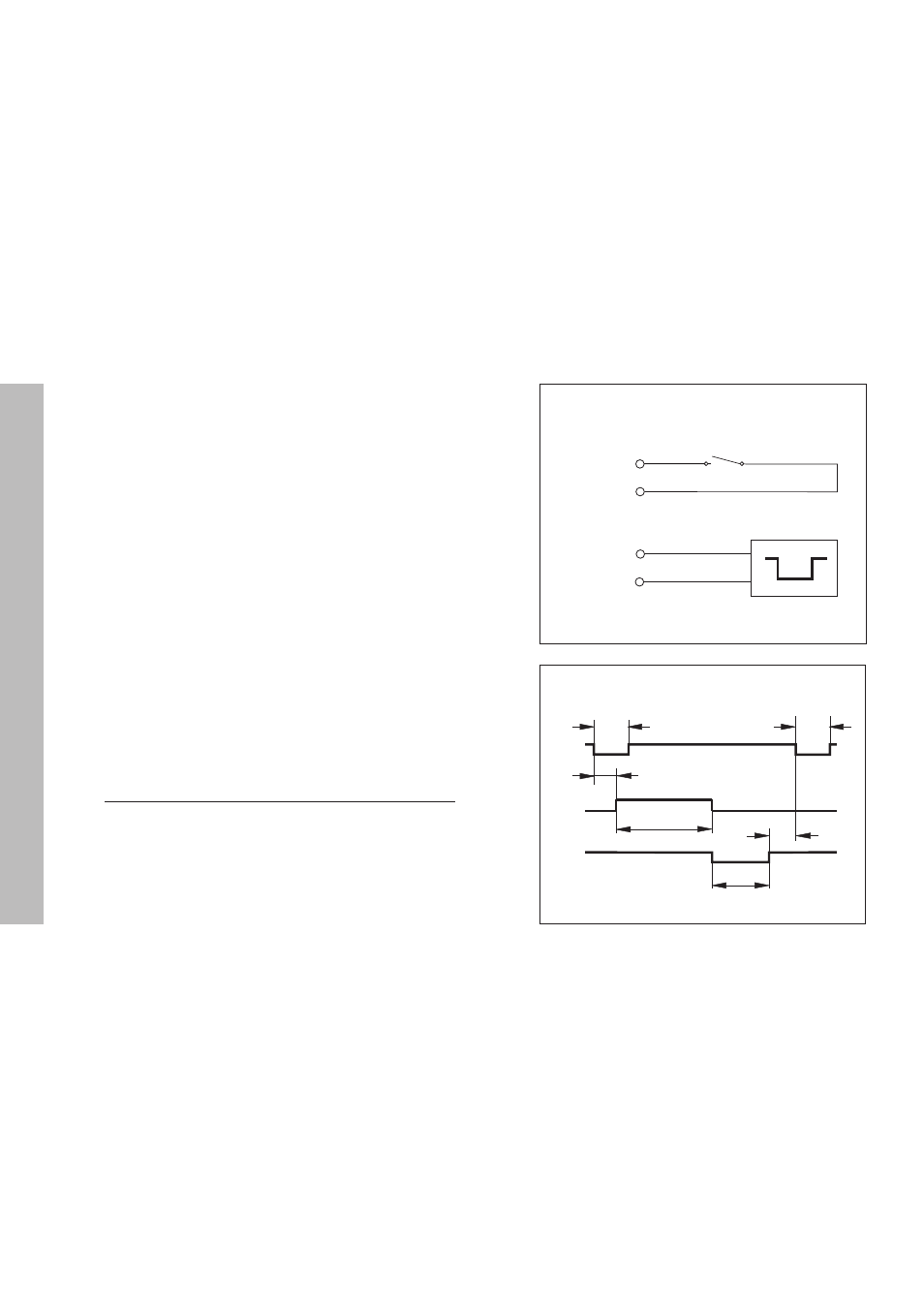
Pin 1(0V)
Pin 9
Pin 8
Pin 1(0V)
EXT(X41)
EXT(X41)
Measured value output over the Contact and Pulse inputs
Measured value output over the Contact input (pin 9 on X41) and Pulse
input (pin 8 on X41) can be triggered when these inputs are closed
against 0 V.
The measured values are output over the TXD line of the RS-232-C
interface.
A commercially available switch can be attached to the Contact input.
This switch generates a signal for data output when it makes contact
against 0 V.
The Pulse input can be triggered with TTL logic devices (for example,
SN74LSXX).
Delay times for data output
Latch signal duration: Pulse
t
e
≥
1.2 µs
Latch signal duration: Contact
t
e
≥
7 ms
Storage delay: Pulse
t
1
≤
0.8 µs
Storage delay: Contact
t
1
≤
4.5 ms
Data output after
t
2
≤
30 ms
Regeneration time
t
3
≥
0
Duration of data output in seconds:
t
D
=
t2
t1
t3
tD
te
te
Next possible signal for measured value output:
t
E
= t
1
+ t
2
+ t
D
+ t
3
[s]
176 x number of axes + 11 x number of blank lines
Baud rate
Measured Value Output