Operating elements, Initial power-up, Operating elements initial power-up – HEIDENHAIN ND 522 Installation User Manual
Page 11: Nd 500 installation instructions
11
ND 500
Installation Instructions
Complete Operating Instructions available at www.heidenhain.de
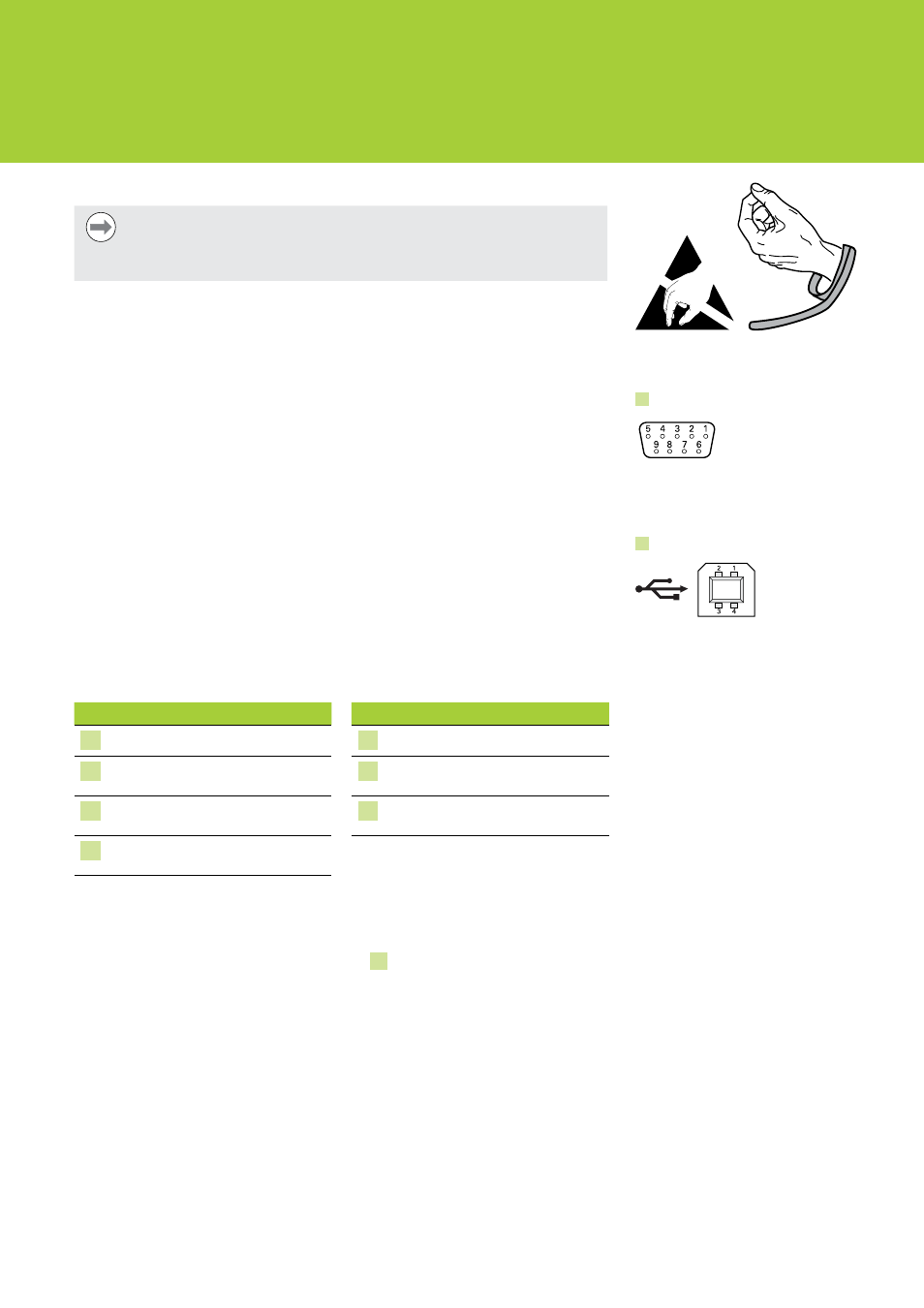
Data interface connections
Notice
This product contains components that can be damaged by electrostatic
discharge (ESD). Observe precautions for handling ESD sensitive devices and
never touch connector pins unless properly grounded.
Connecting an encoder
This product can be used with HEIDENHAIN linear, and rotary encoders that provide
digital TTL level signals. The connecting cable must not exceed 30 meters in length.
To connect an encoder:
X
X
Verify that the power switch is in the off position.
X
X
Connect the axis encoder tightly to it’s connector. An input designator is provided near
each connector located on the rear of the product.
Connecting a USB cable
The USB port is used to communicate with a computer. For more information on USB
communications, refer to the ND 500 Operating Instructions .
To connect a USB cable:
X
X
Verify that the power switch is in the off position.
X
X
Connect a computer USB port to the products USB port located on the rear of the
product, using a USB (type A) to USB (type B) cable.
7. Operating elements
Front
Front (cont)
A LCD screen
E
Arrow keys: Menu navigation
B Soft keys: Change to support
functions
F
Hard key functions: Specific to
milling, or turning functions
C Axis keys: Zero or preset datums
G Power indicator light: LED is
illuminated when power is on
D Numeric keypad: Enter numeric
data
8. Initial power-up
To power-up the product:
X
X
Press the On (supply) side of the power switch 1 to power-up the product.
The startup screen is displayed.
Observe ESD handling precautions
5
X1, X2, X3 - « TTL
4
USB (type B)