Termination plug – Grass Valley Triton Plus Revision Video Routers 14 User Manual
Page 27
Triton Plus - SD/3G-HD/HD -User Manual
27
Router Communication
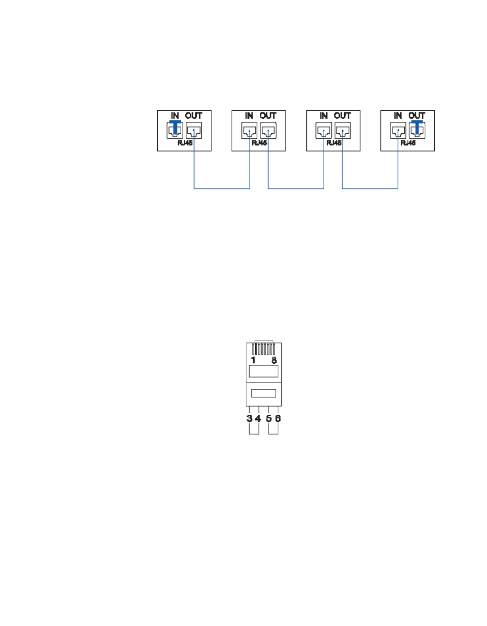
The following connection example (
) shows connection of four
Triton Plus devices with RJ45 connectors and bus termination:
Figure 2. Four Devices Connected Together Using RJ45
Note
Each device at the end of the chain has a termination plug, indicated with the
letter T. This termination plug must be inserted in the correct connection port.
If not, no NCB communication is possible.
Termination Plug
The termination plug that is mentioned in the previous chapter is necessary
when you want to avoid closing the loop with a (long) cable.
The termination plug is a standard RJ45 plug with the following internal
wiring shown in
Figure 3. RJ45 Termination Plug Wiring
Pin 3 is connected to Pin 4
Pin 5 is connected to Pin 6