Connection details – Grass Valley Triton Plus Revision Video Routers 14 User Manual
Page 11
Triton Plus - SD/3G-HD/HD -User Manual
11
Connection Details
Connection Details
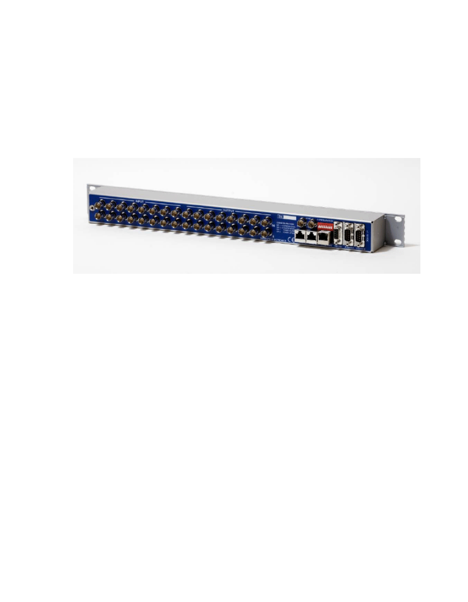
Available connectors at the back panel of the Triton Plus Routers are shown
in
.
Note
shows a 1 RU Triton Plus router. However, the connectors are iden-
tical to the 1 RU also on the 2 RU and 4 RU units. The only connectors that
differ are the applicable signal connectors.
Figure 1. Triton Router Connectors
•
SYNC: Synchronization signal (in). Black burst/composite/tri-level
sync reference input with passive loop-through for vertical interval
switching.
•
LOOP: Synchronization signal (out). Loop-through of SYNC input.
•
NCB IN: Network Control Bus Input. The protocol of this bus is equal,
and compatible to the MIDI bus protocol.
•
NCB OUT: Network Control Bus Output.
•
ETHERNET: Not supported at this time.
•
RS-232: RS-232 for external control protocols.
•
POWER A: ±15VDC Power Input.
•
POWER B: ±15VDC Power Input, redundant supply.
•
CONFIGURATION: Configuration switches (8 pcs).