Table 25. remote 25-pin d connector pinouts, Matrix bnc cabling – Grass Valley Performer-HD User Manual
Page 30
2-12
Performer-HD Instruction Manual
Section 2 — Installation
Matrix BNC Cabling
Input Sources and output Destinations are cabled using 75 Ohm BNCs. All
outputs are duplicated. Any output that is not being used has to be termi-
nated with a 75 Ohm terminator.
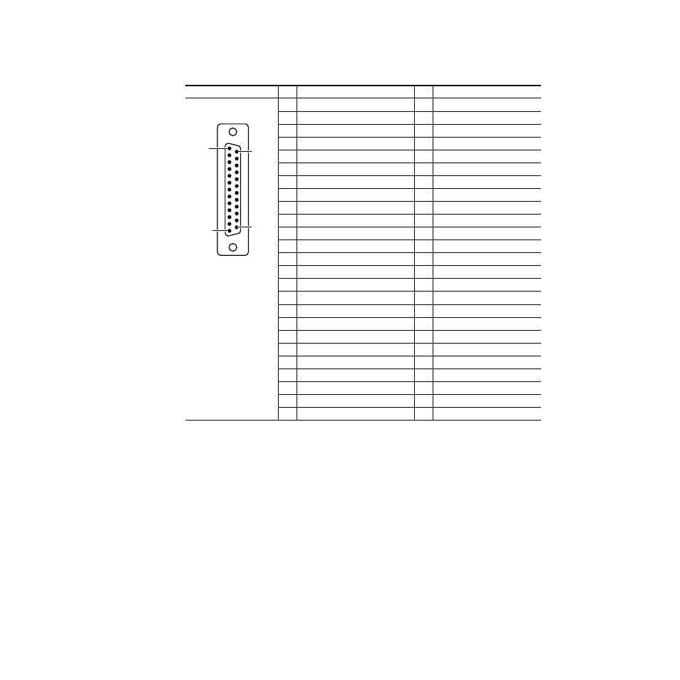
Table 2-5. Remote 25-Pin D Connector Pinouts
Connector
Pin
Remote
Pin
Option
13
VA (bit A of 4-bit binary video status
1
Switch 1
25
VB (bit B of 4-bit binary video status
2
Switch 2
24
VC (bit C of 4-bit binary video status)
3
Switch 3
23
VD (bit D of 4-bit binary video status)
4
Switch 4
5
AA (bit A of 4-bit binary audio status)
5
Switch 5
6
AB (bit B of 4-bit binary audio status)
6
Switch 6
7
AC (bit C of 4-bit binary audio status)
7
Switch 7
8
AD (bit D of 4-bit binary audio status)
8
Switch 8
19
0/
a
(bit O of 5-bit binary source select)
a
/ = Active Low
9
Switch 9
21
A/ (bit A of 5-bit binary source select)
10
Switch 10
22
B/ (bit B of 5-bit binary source select)
11
Switch V (Video Only)
9
C/ (bit C of 5-bit binary source select)
12
SwitchA1 (Audio 1 Only)
20
D/ (bit D of 5-bit binary source select)
13
Switch A2 (Audio 2 Only)
12
KEY ON/ (active low - any button press)
14
GPI (Switch) Common, +5V
10
A ONLY/ (active low - audio only select)
15
Tally Relay 1
11
V ONLY/ (active low - video only select)
16
Tally Relay 2
1
TX RS422+ (RS485 <+>)
17
Tally Relay 3
2
TX RS422– (RS485 <->)
18
Tally Relay 4
14
RX RS422+
19
Tally Relay 5
15
RX RS422–
20
Tally Relay 6
3
TX RS232
21
Tally Relay 7
16
RX RS232
22
Tally Relay 8
4
VI Strobe
23
Tally Relay 9
18
Ground (RS485 )
24
Tally Relay 10
17
≈
+20V DC
25
Tally Common
Pin 1
Pin 13
Pin 14
Pin 25
D-25 Female