Installation, Introduction, Dip switch configurations – Grass Valley Performer-HD User Manual
Page 19: Figure 21. dip switch location and access panel, Section 2 — installation
Performer-HD Instruction Manual
2-1
Section
2
Installation
Introduction
The Performer-HD needs to be configured, to have the buttons labeled, to
be secured in a rack, to have cables attached, and to have power applied be-
fore it is ready for operation.
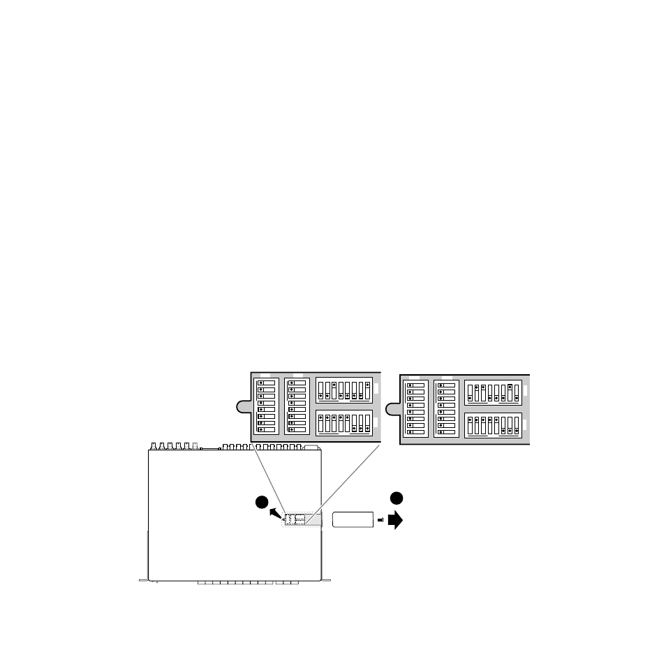
Dip Switch Configurations
Dipswitch banks identified as S1, S2, S3, and S4 are located under a remov-
able panel on the top of the Performer-HD.
shows the location
and default settings of the dipswitch banks.
Figure 2-1. Dip Switch Location and Access Panel
2
1
xxxx_xx_x
1
2
3
4
5
6
OPEN
7
8
1
2
3
4
5
6
OPEN
7
8
123456
OPEN
78
123456
OPEN
78
S3
S1
S2
S4
1
2
3
4
5
6
OPEN
7
8
1
2
3
4
5
6
OPEN
7
8
123456
OPEN
78
123456
OPEN
78
S3
S1
S2
S4
Slave
Master
See also other documents in the category Grass Valley Equipment:
- LDK 5302 (24 pages)
- SFP Optical Converters (18 pages)
- 2000GEN (22 pages)
- 2011RDA (28 pages)
- 2010RDA-16 (28 pages)
- 2000NET v3.2.2 (72 pages)
- 2000NET v3.1 (68 pages)
- 2020DAC D-To-A (30 pages)
- 2000NET v4.0.0 (92 pages)
- 2020ADC A-To-D (32 pages)
- 2030RDA (36 pages)
- 2031RDA-SM (38 pages)
- 2041EDA (20 pages)
- 2040RDA (24 pages)
- 2041RDA (24 pages)
- 2042EDA (26 pages)
- 2090MDC (30 pages)
- 2040RDA-FR (52 pages)
- LDK 4021 (22 pages)
- 3DX-3901 (38 pages)
- LDK 4420 (82 pages)
- LDK 5307 (40 pages)
- Maestro Master Control Installation v.1.5.1 (455 pages)
- Maestro Master Control Installation v.1.5.1 (428 pages)
- 7600REF Installation (16 pages)
- 7600REF (84 pages)
- 8900FSS (18 pages)
- 8900GEN-SM (50 pages)
- 8900NET v.4.3.0 (108 pages)
- Safety Summary (17 pages)
- 8900NET v.4.0.0 (94 pages)
- 8906 (34 pages)
- 8911 (16 pages)
- 8900NET v.3.2.2 (78 pages)
- 8914 (18 pages)
- 8912RDA-D (20 pages)
- 8916 (26 pages)
- 8910ADA-SR (58 pages)
- 8920ADC v.2.0 (28 pages)
- 8920ADC v.2.0.1A (40 pages)
- 8920DAC (28 pages)
- 8920DMX (30 pages)
- 8920ADT (36 pages)
- 8920MUX (50 pages)
- 8921ADT (58 pages)