Figure 22. performer remote to performer-hd, Dip switch settings, Figure 2-2. performer remote to performer-hd – Grass Valley Performer-HD User Manual
Page 20: Performer remote control panel (rear), Performer-hd
2-2
Performer-HD Instruction Manual
Section 2 — Installation
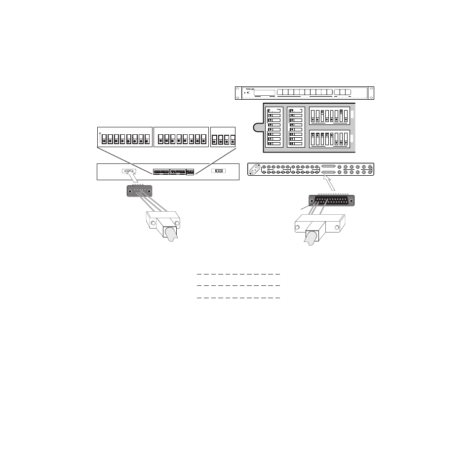
shows the dipswitch settings for a Performer-HD being used
with a Performer Remote Control Panel
.
Figure 2-2. Performer Remote to Performer-HD
1
Performer Remote Control Panel (rear)
Performer
9 pin
Female
RS485 (+) 3
RS485 (-) 8
GND (S) 9
Performer-HD
25 pin
Male
1 RS485 (+)
2 RS485 (-)
18 GND (S)
Cable (max 2000'/610m)
User fabricated
O
25
1
13
14
Performer-HD
1
9
7
5
3
1
2
A2 Out
AC In
AES/EBU 2 In
10
8
6
4
2
1
9
7
5
3
1
2
V Out
Option
Remote
Video In
10
8
6
4
2
1
9
7
5
3
1
2
A1 Out
AES/EBU 1 In
10
8
6
4
2
A1
CH 1/2
A2
CH 3/4
Video
Grass Valley
1
2
3
4
5
6
7
8
9
10
Input Selection
Performer-HD
VAA
Breakaway/Protect
Status/Display
V
A1 CH1/2
On
HD Vid
Present Reclock
Off
A2 CH2/3
A2
CH 3/4
Dip Switch Settings
1
2
3
4
5
6
OPEN
7
8
1
2
3
4
5
6
OPEN
7
8
123456
OPEN
78
123456
OPEN
78
S3
S1
S2
S4
See also other documents in the category Grass Valley Equipment:
- LDK 5302 (24 pages)
- SFP Optical Converters (18 pages)
- 2000GEN (22 pages)
- 2011RDA (28 pages)
- 2010RDA-16 (28 pages)
- 2000NET v3.2.2 (72 pages)
- 2000NET v3.1 (68 pages)
- 2020DAC D-To-A (30 pages)
- 2000NET v4.0.0 (92 pages)
- 2020ADC A-To-D (32 pages)
- 2030RDA (36 pages)
- 2031RDA-SM (38 pages)
- 2041EDA (20 pages)
- 2040RDA (24 pages)
- 2041RDA (24 pages)
- 2042EDA (26 pages)
- 2090MDC (30 pages)
- 2040RDA-FR (52 pages)
- LDK 4021 (22 pages)
- 3DX-3901 (38 pages)
- LDK 4420 (82 pages)
- LDK 5307 (40 pages)
- Maestro Master Control Installation v.1.5.1 (455 pages)
- Maestro Master Control Installation v.1.5.1 (428 pages)
- 7600REF Installation (16 pages)
- 7600REF (84 pages)
- 8900FSS (18 pages)
- 8900GEN-SM (50 pages)
- 8900NET v.4.3.0 (108 pages)
- Safety Summary (17 pages)
- 8900NET v.4.0.0 (94 pages)
- 8906 (34 pages)
- 8911 (16 pages)
- 8900NET v.3.2.2 (78 pages)
- 8914 (18 pages)
- 8912RDA-D (20 pages)
- 8916 (26 pages)
- 8910ADA-SR (58 pages)
- 8920ADC v.2.0 (28 pages)
- 8920ADC v.2.0.1A (40 pages)
- 8920DAC (28 pages)
- 8920DMX (30 pages)
- 8920ADT (36 pages)
- 8920MUX (50 pages)
- 8921ADT (58 pages)