Connecting to power, Installation – Grass Valley EC9535 v.1.1 User Manual
Page 24
16
Installation
Connecting to Power
opens. The alarm turns OFF when the connection between Alarm_COM and the alarm pin closes
again.
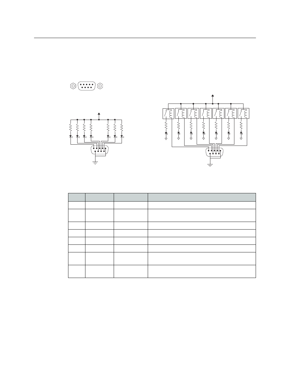
To create an indicator box, connect to the ‘ALARM’ connection using a DE9 female connector,
wiring as shown in Figure 2-7. Each pin monitors a specific function and activates a specific
alarm.
Fig. 2-7: Alarm Connections and On/Off Switches
The following lists each DE9 pin and the associated alarm. The pin number listed corresponds to
the pin numbers in Figure 2-7 on page 16:
Connecting to Power
The EC9535 uses a proprietary power supply (PS0007) to connect to an AC power source (90–
230 VAC, 50–60 Hz).
Typical Circuit 1
Customer-supplied relay
contacts NC, (but open during
alarm condition)
External Power,
30VDC max, 150mA max
Normally ON, the LEDs turn off to indicate failure
1
COM
Normally OFF, the LEDs turn on to indicate failure
30VDC max, 150mA max
External Power
1
1
2
3
4
5
6
7
8
9
1
2
3
4
5
Alarm COM
Alarm 1
Alarm 2
Alarm 3
Alarm 4
8
7
8
9
Alarm 5
Alarm 6
Alarm 7
Alarm COM
Typical Circuit 2
COM
PIN
Signal
Description
Possible Conditions Causing the Alarm
1, 9
Alarm_COM
Common
Common connection for all alarm pins.
2
Alarm_1
Major Alarm
Indicates missing reference inputs, or missing power sup-
plies.
3
Alarm_2
Minor Alarm
Alarm_3, or Alarm_4, or Alarm_5, or Alarm_6
4
Alarm_3
Power Supply
Missing power supply module.
5
Alarm_4
Video Ref
Missing Video Ref 1 or Video Ref 2.
6
Alarm_5
AES Ref
Not used in EC9535.
7
Alarm_6
Fans or Tempera-
ture
Indicates a fan failure or module over temperature.
8
Alarm_7
Control Module
Health
Any control module not “healthy.”