Making router connections, How to make router control connections, Making router – Grass Valley EC9535 v.1.1 User Manual
Page 20: Connections, Installation, Ωbnc terminator
12
Installation
Making Router Connections
3 Connect the other end of the cable to the SMS7000 system controller. For detailed instruc-
tions, refer to the SMS7000 documentation.
4 On the unused GSC Node Bus connection, terminate the loop-through by installing a 75
Ω
BNC terminator.
Making Router Connections
In order for a NV8288, NV8288-Plus or NV8500 Family router to communicate with a SMS7000
system controller, the router must be connected to an EC9535. The router is connected using
the serial control system connections, located on the rear of the EC9535, and a cable provided
by Miranda (WC0152). The proprietary cable is 20 feet (6.096 meters) long with two DE9 (a.k.a.
DB9) connectors on each end for a total of four DE9 connectors.
The serial control ports are divided into two sets that enable the primary control card or the
secondary control card in the EC9535 frame to communicate with the corresponding control
card in the router frame.
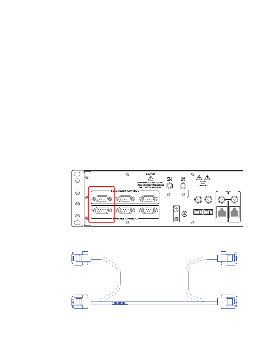
How to Make Router Control Connections
1 Locate the serial control connections on the rear of the router, as shown in Figure 2-3. Serial
control connections are labeled ‘PRIMARY CONTROL’ for the primary control card and ‘SEC-
ONDARY CONTROL’ for the secondary control card.
Fig. 2-3: Serial Control Connections (Rear View)
2 Locate the cable WC0152 provided with the EC9535. The cable has four DE9 connectors as
shown:
Fig. 2-4: WC152 Cable for connecting to router
SEC
CTRL
LOOP
THRU
10/100 BT
10 B 2
PRI
CTRL
10 B 2
10/100 BT
AES
REF 1
AES
REF 2
DIAG
DIAG
CTRL 1
CTRL 2
CTRL 1
CTRL 2
Serial Connections to
Control System
P1
P2
P4
P3