Time code reference connection, System alarm, Time code reference connection system alarm – Grass Valley EC9535 v.1.1 User Manual
Page 15: Reference manual, Fig. 1-11: system alarm connection (rear view), Time code connector, System alarm connector
7
EC9535
Reference Manual
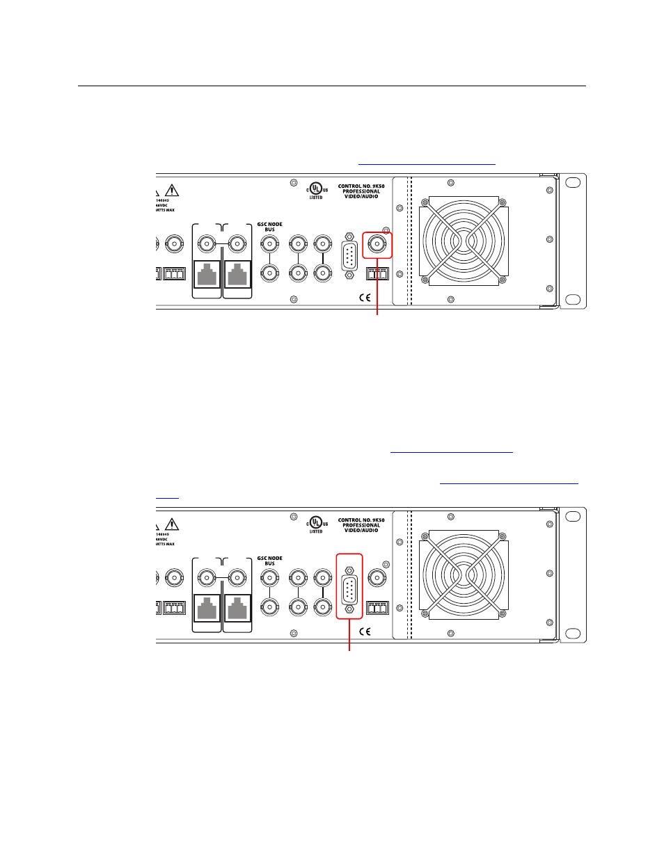
Time Code Reference Connection
There is a single Time Code reference connection labeled ‘TIME CODE’, as shown in Figure 1-10.
This reference is not currently used in the EC9535, but provided for future flexibility. For more
information, contact Technical Support. (See
Grass Valley Technical Support
Fig. 1-10: Time Code Reference Connection (Rear View)
System Alarm
The EC9535 has a system alarm that sends notification of a malfunction, such as when a fan or
power supply is not functioning properly. The alarm connection can be connected to external
equipment that display visual signals when an alarm is activated. Creation of an external alarm
indicator is outside the scope of this manual, however basic instructions on wiring the alarm
connection for external monitoring is provided. See
The alarm connection is labeled ‘ALARMS’ and is located on the rear of the EC9535, as shown in
Figure 1-11. For instructions on making alarm connections, see
Fig. 1-11: System Alarm Connection (Rear View)
VIDEO
REF 2
VIDEO
REF 1
ALARMS
TIME
CODE
LOOP
LOOP
LOOP
SEC
CTRL
LOOP
THRU
10/100 BT
10 B 2
PRI
CTRL
10 B 2
10/100 BT
AES
REF 1
AES
REF 2
E146905
Time Code Connector
VIDEO
REF 2
VIDEO
REF 1
ALARMS
TIME
CODE
LOOP
LOOP
LOOP
SEC
CTRL
LOOP
THRU
10/100 BT
10 B 2
PRI
CTRL
10 B 2
10/100 BT
AES
REF 1
AES
REF 2
E146905
System Alarm Connector