Addressing requirements, Chassis address setting requirement, Cabling requirements – Grass Valley K2 Level 3 RAID Dec.09 2005 User Manual
Page 26: Chapter 2 level 3 raid installation information
26
Level 3 RAID Instruction Manual
November 23, 2005
Chapter 2 Level 3 RAID Installation Information
Addressing requirements
There are two addresses for the K2 Level 3: the Fibre Channel Arbitrated Loop
address ID (FC-AL address ID) and the chassis address. If you have a custom system
that needs multiple primary RAID chassis connected to an FC switch, consult your
Grass Valley representative.
Chassis address setting requirement
The chassis address for a K2 Level 3 primary RAID chassis is pre-set at 0 and does
not need to be configured.
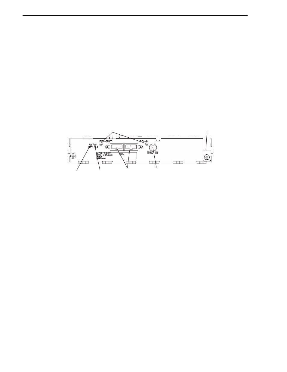
Each Level 3 Expansion expansion chassis must have its chassis address configured.
This is set by the chassis address switch, which is located on the expansion adapter.
The following figure identifies the switch.
Set the switch as explained in the K2 Storage System Instruction Manual.
NOTE: When the switches of the left and right adapters are set differently, the
FAULT LEDs blink and the Expansion chassis is not started. If different values are
set, turn off the power of the system including the Expansion chassis, re-set the
values to
1
, and turn on the power again.
Cabling requirements
It is recommended that you use the Fibre Channel cables shipped with your K2 Level
3 Expansion Chassis when making connections. For cable specifications, refer to
Optical cables must meet the appropriate 2-Gbit FC-AL loop standards. You must use
this type of cable to connect a host to the K2 Level 3 controller.
Copper cables must meet the appropriate standards for 2-Gbit FC-AL loops. You
must use this type of cable to connect Expansion chassis.
Do not leave an unused (that is, dangling) cable connected to a Fibre Channel port
because it may cause excess noise on the loop.
NOTE: Also refer to the K2 Storage System Instruction Manual for cabling
diagrams and step-by-step instructions.
(4) LINKUP LED
(6) Ejector
(1) READY LED
(2) FAULT LED
(3) FC connectors
(FC-IN/FC-OUT)
(5) ENC ID switch
Chassis address
switch