Grass Valley FXC-S201 User Manual
Page 24
FXC-S201 Unit
System Switch
Mode Switch
4W Switch
2W Power Switch
#A in drawing
Match Intercom
2W
NA
EXT
#B in drawing
Match Intercom
2W
NA
INT
20
Setting Up the CommLink FXC-S201
Connecting a Matrix Frame System with Two Remote Matrix Stations
Connecting a Matrix Frame System with Two Remote Matrix Stations
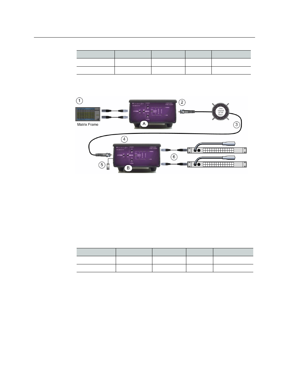
Fig. 3-2: Connecting a Matrix Frame System with Two Remote Matrix Stations
Connect the Intercom Matrix (1) and CommLink FXC-S201 Fiber Optic Intercom Link Unit
"A" (2). Run a Single Strand Fiber Cable, or dual cable if used (3) between CommLink FXC-
S201 Fiber Optic Intercom Link Unit "B" (4) and power the CommLink FXC-S201 Fiber Optic
Intercom Link using the appropriate power supply (5).
Connect your two intercom Matrix Stations (6) and provide power locally. Remember that
CommLink FXC-S201 Fiber Optic Intercom Link "A" must have a WDM factor different from
CommLink FXC-S201 Fiber Optic Intercom Link "B." You must use a WDM @1550nm unit at
one end of the fiber cable and a WDM@1310 at the other end of the fiber cable.
FXC-S201 Unit
System Switch
Mode Switch
4W Switch
2W Power Switch
#A in drawing
Match Intercom
4W
MTX
NA
#B in drawing
Match Intercom
4W
STA
NA