Commlink fxc-s201 front and rear panel components, Area a - system configuration switches – Grass Valley FXC-S201 User Manual
Page 12
8
System Overview
CommLink FXC-S201 Front and Rear Panel Components
CommLink FXC-S201 Front and Rear Panel Components
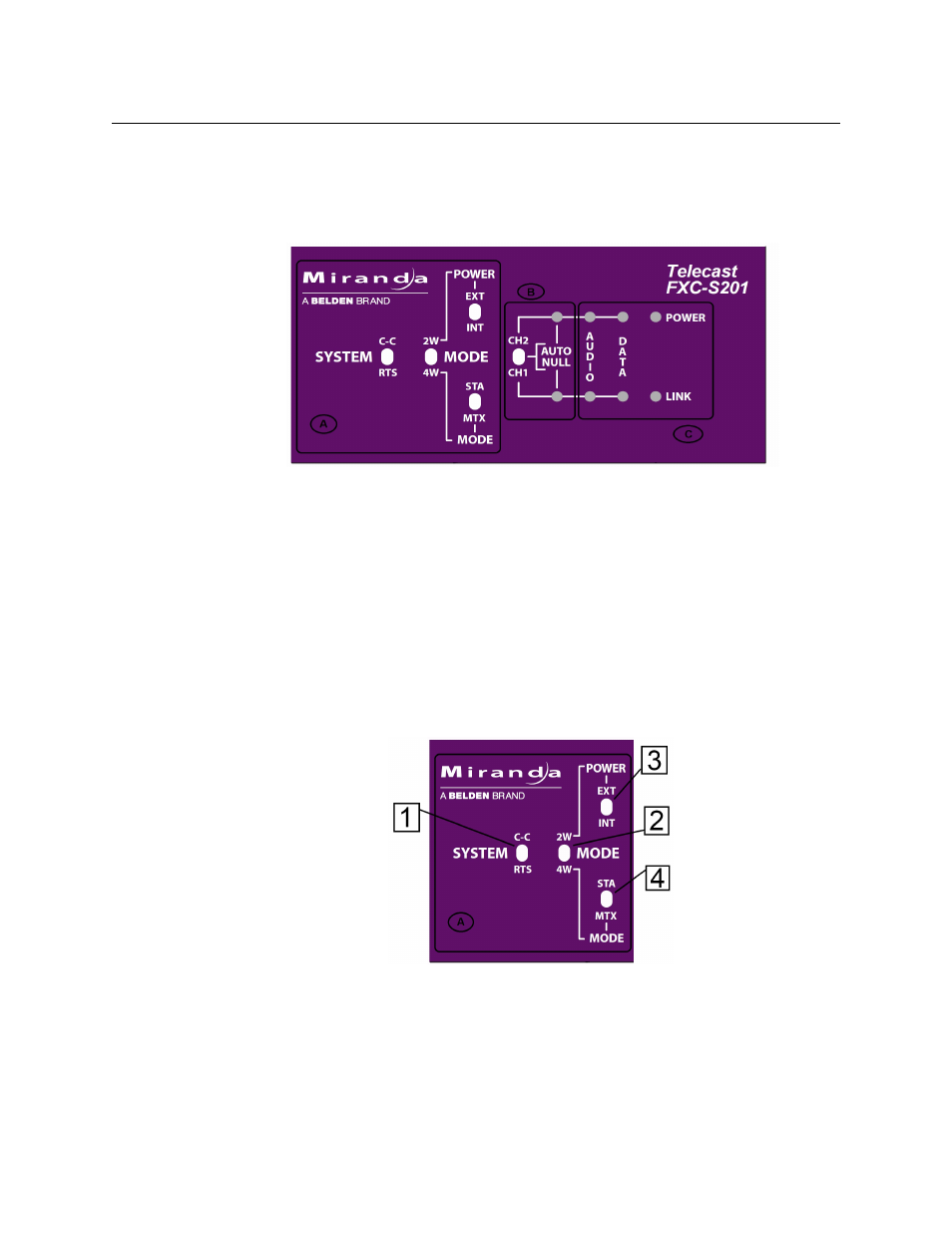
CommLink FXC-S201 Fiber Optic Intercom Link Front Panel
Fig. 2-5: CommLink FXC-S201 Fiber Optic Intercom Link Front Panel
The CommLink FXC-S201 Fiber Optic Intercom Link has three features:
• Area A: System Configuration Switches
• Area B: Auto Null Control and Indicators
• Area C: System Status Indicators
Area A - System Configuration Switches
The four switches in this section allow the configuration of the CommLink FXC-S201 Fiber
Optic Intercom Link for the particular intercom environment in use. See
CommLink FXC-S201Usage Scenarios
on page 19 below for examples of how these
switches interact.
Fig. 2-6: System Configuration switches
• 1: System Switch - sets the CommLink FXC-S201 Fiber Optic Intercom Link in either RTS
mode or Clear-Com (C-C) mode
• 2: Mode Switch - sets the CommLink FXC-S201 Fiber Optic Intercom Link in either Two
Wire (2W) or Four Wire (4W) mode