Clear-com mode wiring and switch settings, Commlink fxc, Commlink fxc-s201 fiber optic intercom link – Grass Valley FXC-S201 User Manual
Page 16: Matrix and station connectors
12
System Overview
CommLink FXC-S201 Fiber Optic Intercom Link Matrix and Station Connectors
CommLink FXC-S201 Fiber Optic Intercom Link
Matrix and Station
Connectors
Both the RTS and Clear-Com system matrix systems use data wiring to carry intercom audio
and data. Clear-Com systems use an 8-wire "network" cable with RJ45 connectors. RTS
systems use a 6-wire cable with RJ11 connectors similar to standard telephone wiring.
However, telephone wiring will not work as it is only 4-wire.
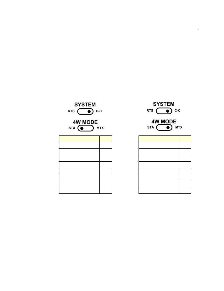
The CommLink FXC-S201 Fiber Optic Intercom Link Configuration is shown for each
intercom mode. The switch position is indicated. In all cases, the 4W/2W switch is in the 4W
position.
Clear-Com Mode Wiring and Switch Settings
Signal
Pin #
Signal
Pin #
RS-422 data receive (+)
1
RS-422 data send (+)
1
RS-422 data receive (–)
2
RS-422 data send (–)
2
Audio receive (+)
3
Audio send (+)
3
Audio send (+)
4
Audio receive (+)
4
Audio send (–)
5
Audio receive (–)
5
Audio receive (–)
6
Audio send (–)
6
RS-422 data send (+)
7
RS-422 data receive (+)
7
RS-422 data send (–)
8
RS-422 data receive (–)
8
To Remote Station
To Matrix Frame
Fig. 2-10: Clear-Com Mode - Switch Settings and 4W Data Connector Pinouts