Cameraman ports and jacks, Page 5 – Grass Valley 3-CCD ANALOG CameraMan Rev.D1 User Manual
Page 8
3-CCD ANALOG Camera
Page 5
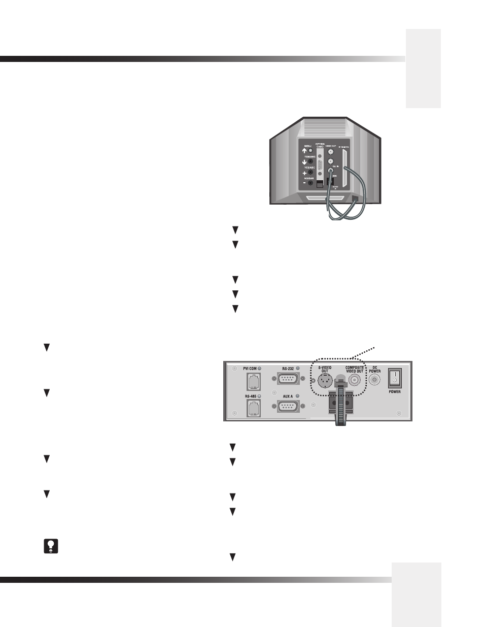
The back of the CameraMan 3-CCD ANALOG Camera has a variety of ports and jacks used
to connect the camera to other video and camera control components in a system.
CameraMan Ports and Jacks
PVI COM Jack– Used by certain devices
as a communication interface to the camera system.
(For example, a hard-wired keypad would attach here).
This is a standard 6-conductor RJ-11 jack.
RS-485 Jack–- Used for RS-485 communications
between the camera system and other Grass Valley
devices. This jack can be used to network multiple
cameras or to connect appropriate, approved
peripherals using the supplied T-connector. This is a
standard 4-position modular handset jack.
Auxiliary
Communication
Port–
Provides
communications to select Grass Valley peripherals and
provides capability for future expansion.
RS-232 Port–Provides RS-232 communications to
external devices such as PC's or other vendor control
systems. This connector is a standard DB-9 (female)
connector.
MENU – Turns on the on-screen menu for appearance
adjustments. Also used to scroll upward through the
on-screen menus.
ITEM/AWC – When in shooting mode, the automatic
white balance control can be set with this switch. It can
also be used to scroll downward through the on-screen
menus.
YES/ABC – When in shooting mode, the automatic black
balance control can be set with this switch. It is also
used to display and increase the value of the sub-menus
of the main on-screen menu.
NO/BAR – When in shooting mode, the color bar and the
shooting conditions are alternately indicated by pressing
this switch. This is also used to scroll downward through,
or lower the value of sub-menu items.
OPTION CARD/COMPONENT OUT – An Analog R/G/B,
Y/C, or Y/Pr/Pb component signal is provided at this
DB-9 connector.
Ports and Jacks
Non-functional on
3-CCD Cameras
S-Video Jack–- Non-functional.
Cable Restrainer– Helps keep cables from
becoming disconnected, or hindering the pan and
tilt capabilities of the camera.
Composite Video Jack– Non-functional.
DC Power Jack– Power input for the CameraMan
Camera. Plug only the suppoied power supply
into this jack. No other types of power
supplies should be used.
Power– Used to power on/off the CameraMan
Camera.
VIDEO OUT – This is a Composite Video Out signal.
G/L IN – A GEN LOCK BNC connector used to
synchronize the camera by connecting it to the network's
Video Timing Source.
IRIS – Input terminal for lens iris control.
DC12V IN – Not Used.
I/F REMOTE – Allows communication with the pan/tilt
unit.
Back of Camera Shroud
The PVTV SHOT Director can communicate with the
cameras through either the RS-485 or RS-232 port.