Connecting camera control devices, Page 11 – Grass Valley 3-CCD ANALOG CameraMan Rev.D1 User Manual
Page 14
3-CCD ANALOG Camera
Page 11
Connecting Camera Control Devices
There are several ways to control the CameraMan’s movement. The information below explains how to
connect and configure the optional Camera Control Keypad, or the PVTV SHOT Director.
Connecting Optional Camera Control Devices
Note: Do not use the Camera Control Keypad and the CameraMan
SHOT Director at the same time
Camera Control Keypad (or Tracking System Keypad)
The optional Camera Control Keypad controls the camera’s movement via
wireless RF technology (up to 60 feet), or hard-wired connection (up to 250
feet). If you choose to use a Camera Control Keypad in the hard-wired mode,
follow these directions for installation.
1. Using the 25’ CameraMan Keypad Cable included with your camera,
connect one end of the cable to the RJ-11 type jack located in the
battery compartment of the keypad.
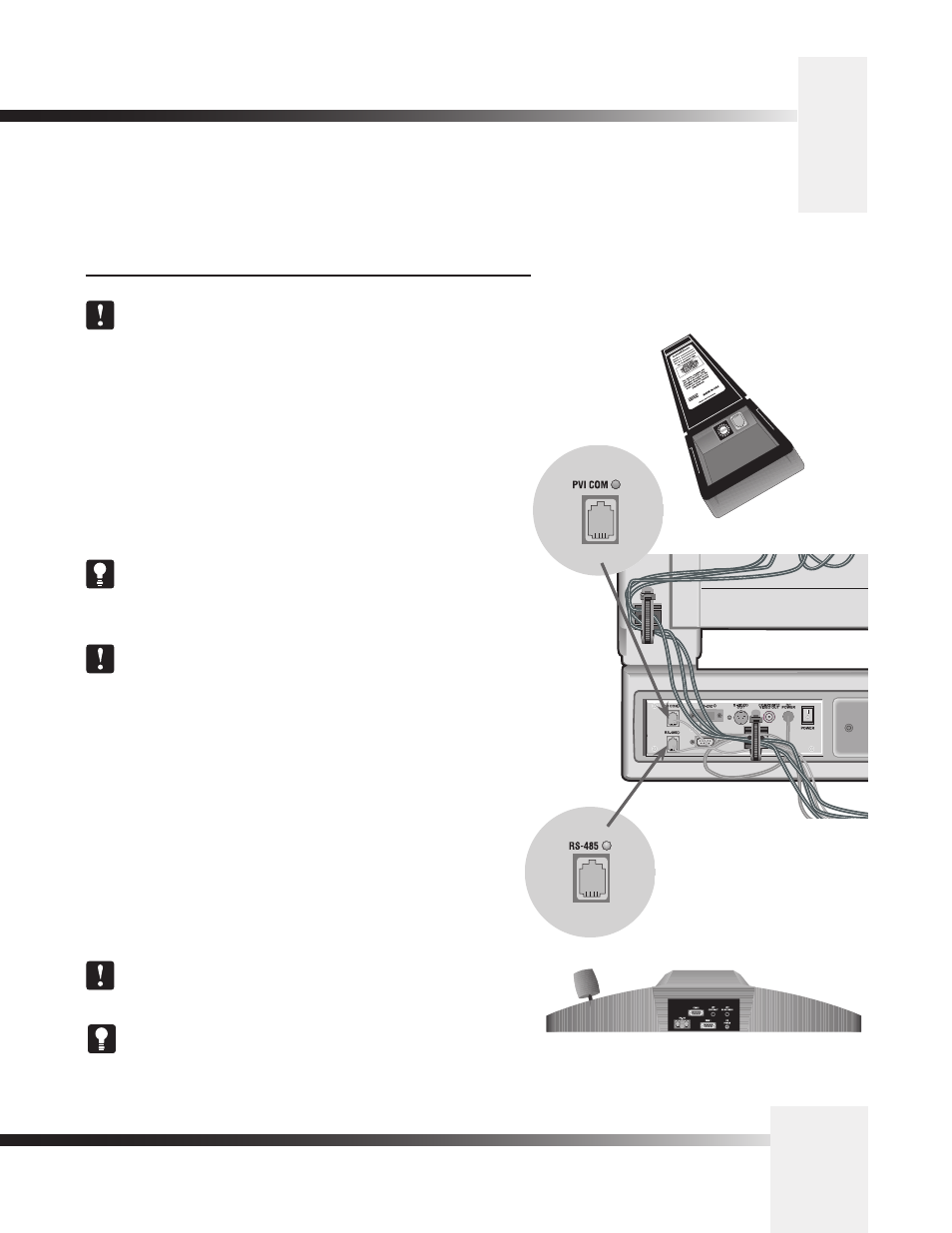
2. Connect the other end of the cable to the RJ-11 type jack on the back
of the camera, labeled PVI COM.
Tip: When the system is powered on, the light on the keypad
should illuminate momentarily, indicating the keypad is ready for
operation. The light located above the PVI COM port is used to
indicate communication activity.
Note: Using cable other than the supplied cable for the PVI
COM port may cause damage.
PVTV SHOT Director
The optional PVTV SHOT Director multi-camera controller can be connected
in hard-wired mode only. Follow these directions to connect the PVTV SHOT
Director to the CameraMan.
1. Using a standard RS-485 cable, connect one end of the cable to one
of the RS-485 jacks (either one) on the back of the PVTV SHOT
Director.
2. Connect the other end of the cable to:
• The jack labeled RS-485 on the back of the CameraMan
connector box for single camera applications, or
• The T-Connector for multiple-camera applications. Then use
the provided 3’ CameraMan Communication Cable to connect
the T-connector to the camera’s RS-485 jack.
Note: If using a Camera Control Keypad or PVTV SHOT Director,
refer to its operations manual. If it is unavailable, contact your local
reseller or Grass Valley.
To use the RS-232 port for communication between the camera and
PVTV SHOT Director, connect one end of the cable to the RS-232
port on the CameraMan Connector Box (Mini Docking Station), and
connect the other end of the RS-232 cable to the COM 1 Port
on the PVTV
PVTV SHOT Director
connected via RS-485
Camera Control
Keypad
connected via
PVI COM