Connecting to the camera system, Page 9, Connecting the camera control cables – Grass Valley 3-CCD ANALOG CameraMan Rev.D1 User Manual
Page 12: Connecting the rgb output, See appendix h for output signal selection details, Ccd analog camera
3-CCD ANALOG Camera
Page 9
Connecting to the Camera System
Follow the instructions below to begin connecting the camera to the system.
Tip: After connecting each cable to the camera, let it hang
loosely behind the camera. Then follow the instructions in the
“Restraining the Cable Connections” section before attaching the
other ends of the cable to other equipment. This will relieve
undue stress on the cables, allowing the camera to move freely.
Connecting The Camera Control Cables
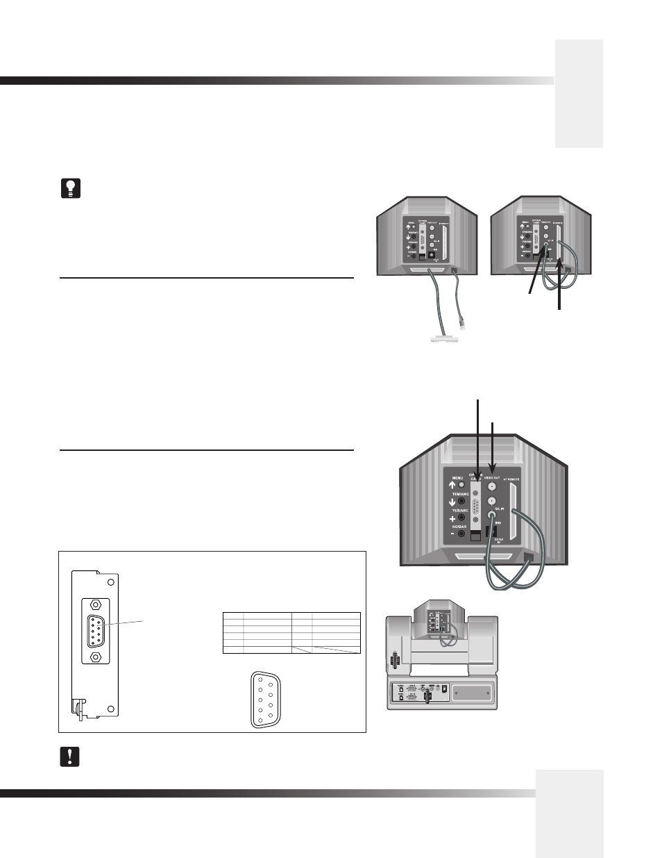
On the back of the camera shroud, there are two cables. These control
the camera’s lens, power and video signals. These must be attached for
the camera to operate properly.
• Connect the 12-pin male connector (#1) to the IRIS jack.
• Connect the 50-pin SCSI connector (#2) to the I/F REMOTE jack.
Connecting The RGB Output
The 3-CCD ANALOG Camera supports IV[p-p] (75 ohm) video output.
For a Composite signal, connect to the BNC jack labeled VIDEO OUT on
the back of the camera shroud, using a standard coaxial cable with a BNC
connector. For a YC/YPrPb/RGB Component signal, connect to the DB-9
connector on the back of the camera.
1
2
2
1
YC/YPrPb/RGB
Component Video Out
Rear View of ANALOG
Camera
IV[p-p] 75 ohm
Composite Video Out
Video/RGB Output Connector [VIDEO/RGB]
Composite signals, RGB/YPrPb/YC component signals,
and synchronizing signals are output.
These output signals can be selected using the menu.
Use the special cable WV-CA9T5 (Dsub-BNC) or WV-
CA9T9 (Dsub-Dsub) to connect to it.
VIDEO/RGB
Video/RGB output
connector
1
2
3
4
5
9
8
7
6
Pin assignments
Pin No.
1
2
3
4
5
Signal
COMPOSITE GND
VIDEO GND
R/Pr/C
G/Y/Y
B/Pb/–
7
8
9
SYNC
SYNC GND
NC
6
COMPOSITE
Pin No.
Signal
See Appendix H for output signal selection details.