Onboard module configuration, Remote control lockout, Audio output impedance – Grass Valley 8920DMX User Manual
Page 14: D module configuration
14
8920DMX Instruction Manual
Configuration
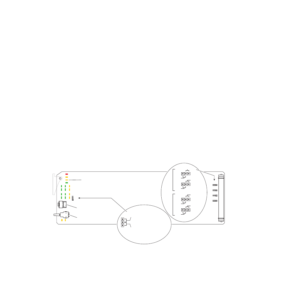
Onboard Module Configuration
The 8920DMX module can be locally configured using the jumpers, the
rotary switch, and the paddle switch shown in
. These components
perform the following:
•
Jumpers – set control mode for Local only or Remote and Local, and
select audio output type and impedance.
•
Function (rotary) switch – selects a desired configuration parameter (0
through 9, A through F), although not all positions are used.
•
SW1 (paddle) switch – initiates a configuration parameter selection.
•
CONF (configuring) LED – when on, indicates the module is initial-
izing or processing configuration information.
Remote Control Lockout
When a jumper is placed across pins 2 and 3 of jumper block JP10 (see
), module output mode settings are adjustable from the Local
on-board switches only. To have both Local and Remote access, set the
jumper across pins 1 and 2.
Audio Output Impedance
The desired audio type and output impedance must be selected as bal-
anced 110
Ω
or unbalanced 75
Ω
with jumpers JP12 and JP13 (AES 1) and
JP13 and JP15 (AES 2) shown in
.
Figure 5. Module Configuration Switches and LEDs
SW1 – Function Rotary Switch
SW2 – Selection Paddle Switch
CONF (yellow)
8038_06r1
JP10
LOCAL –
REMOTE –
jumper across these pins
locks out remote control
jumper across these pins
enables remote and
local control
Remote Control Lockout
Audio Output Impedance
JP10
JP12
JP13
JP14
JP15
JP12
75
Ω
unbal.
AES 1
110
Ω
bal.
JP13
75
Ω
unbal.
110
Ω
bal.
75
Ω
unbal.
JP14
110
Ω
bal.
JP15
75
Ω
unbal.
110
Ω
bal.
AES 2
1
2
3