Power up, Operation indicator leds – Grass Valley 8920DMX User Manual
Page 11
8920DMX Instruction Manual
11
Power Up
Power Up
The LED indicators and configuration switches are illustrated in
.
Upon power-up, the green PWR LED should light and the yellow CONF
LED should light while the module initializes (less than 2 seconds).
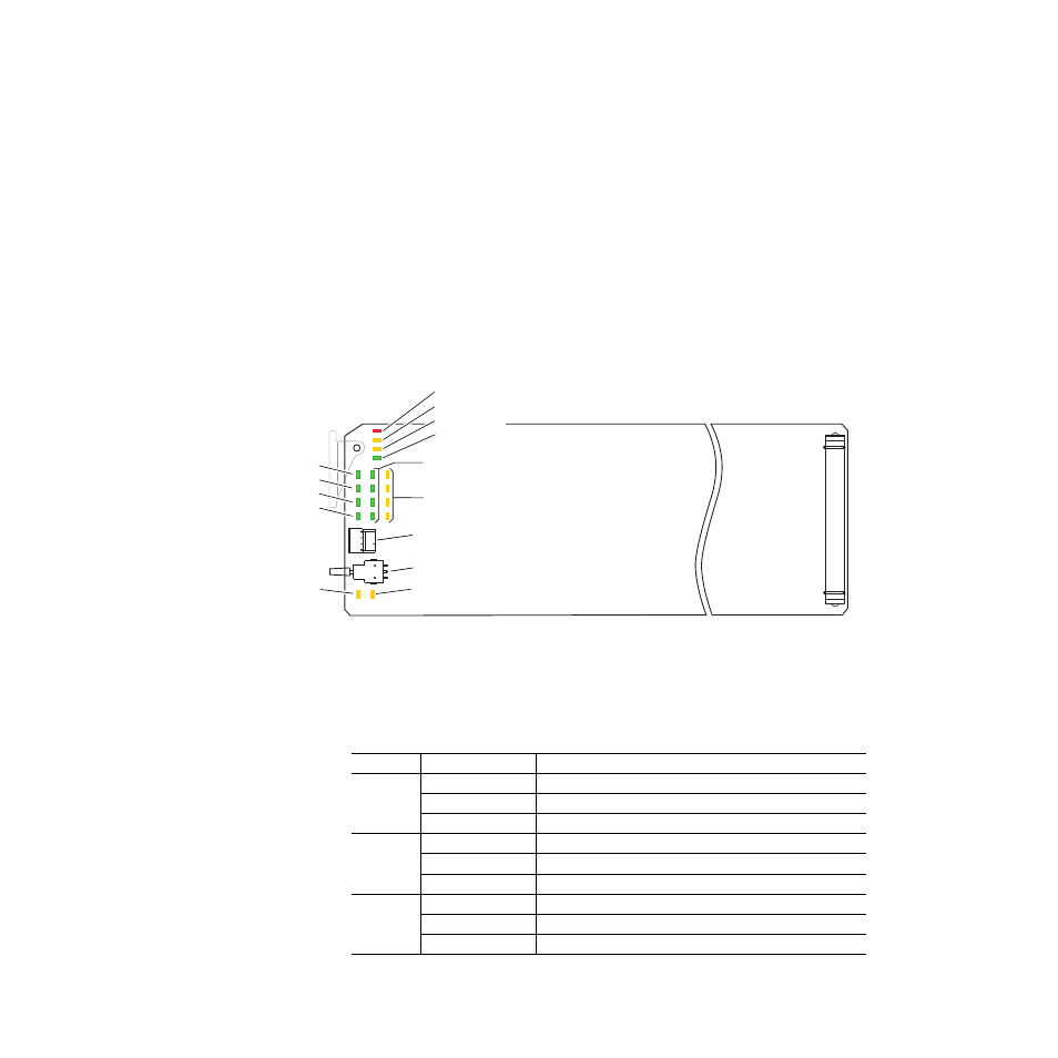
Operation Indicator LEDs
With factory default configuration and a valid SD input containing
AES/EBU audio groups, the green PWR LED, an SD format LED (either
525 or 625), one or more Signal Present LEDs should be on. The appropriate
yellow Extract LED (G1 through G4) will indicate which audio group the
module is configured to extract.
Figure 4. Operation Indicator LEDs
A red FAULT LED indicates an error situation and, with the other LEDs,
can indicate the operational conditions presented in
. The table
describes signal output and LED indications for various input/reference
combinations and user settings.
Table 2. Indicator LEDs and Conditions Indicated
LED
Indication
Condition
FAULT
(red)
Off
Normal operation.
On continuously
Module has detected an internal fault. (Refer to
.)
Flashing
Configuration problems. Check inputs and settings. Missing video or group.
COMM
(yellow)
Off
No activity on frame communication bus.
3 Quick Pulses
Location Command received by the module from a remote control system.
Short flash
Activity present on the frame communication bus.
CONF
(yellow)
Off
Module is in normal operating mode.
On continuously
Module is initializing, changing operating modes or updating firmware.
3 Quick Pulses
Location Command received by the module from a remote control system.
SW1 – Function Rotary Switch
G1
G4
EDH LED (yellow)
SW2 – Select/Adjust Paddle Switch
8038_05
FAULT (red)
COMM (yellow)
CONF (yellow)
PWR (green)
Audio G1 through G4
Signal Present (green)
Audio G1 through G4
Extract (yellow)
625 (green)
525 (green)
AES 1(green)
AES 2 (green)
24-bit LED