Cabling, Input, Outputs – Grass Valley 8920DMX User Manual
Page 10
10
8920DMX Instruction Manual
Installation
Cabling
Input
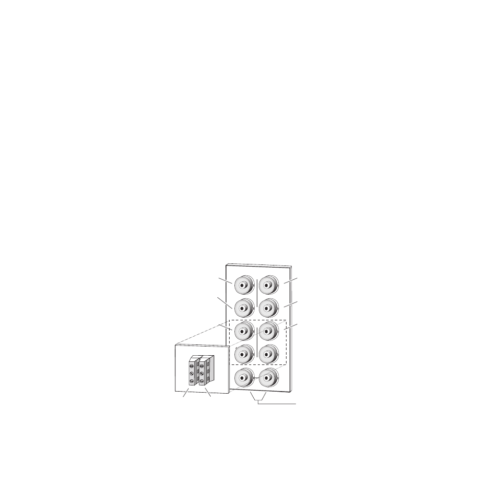
The SD video stream is connected to the looping input BNC at J9 or J10. If
not looping the signal to other equipment, terminate the unused connector
into 75
Ω
.
Outputs
The 8920DMX provides four SD output streams—J1 through J4. The desti-
nation equipment should have a 75
Ω
input impedance or loop through
inputs that are terminated into 75
Ω
.
For unbalanced AES/EBU audio outputs, connect cables to BNCs J5 and J6.
For applications requiring balanced audio outputs, use the terminal post
adapter shown in
to connect up to two balanced AES/EBU output
cables. The adapter mounts on the plus and minus BNC pairs J5/J7 and
J6/J8. This adapter ships with the 8920DMX-110 model or can be ordered
separately if required.
Note
Jumpers JP12 – JP15 on the module circuit board must be set for the correct
audio output impedance (balanced 110
Ω
or un balanced 75
Ω
). Refer to
.
Figure 3.
8920DMX
Input/Output Connectors
J9 J10
IN
J3
J5
J7
J4
J6
J8
J2
J1
8038-02R2
Loop-through
SD Input
SD Output 1
SD Output 3
AES Output 1
unbalanced 75
Ω
SD Output 2
SD Output 4
AES Output 2
unbalanced 75
Ω
Adaptor for balanced 110
Ω
outputs, connects to BNCs J5 - J8.
X
O
U
T
J1
R+
GND
R–
L+
GND
L–
Grass Valley
Adaptor
AES
Output 1
AES
Output 2