Configuring output mode, Remote control lockout – Grass Valley 2020ADC A-To-D User Manual
Page 18
18
2020ADC — Instruction Manual
Configuration
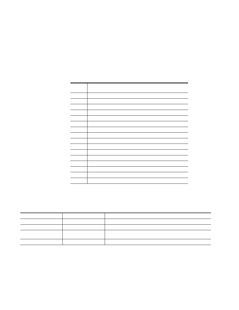
Configuring Output Mode
The 2020ADC provides thirteen possible output configurations as shown
in
. The module can be configured using the rotary switches shown
in
. To make a configuration setting, rotate the switch
for CH 1/2 and CH 3/4 to the desired output configuration. The 16-posi-
tion rotary switch selects one of 13 possible output modes. Positions B and
C are not used and positions 0 and F select the same mode—the factory
default.
provides the possible input conditions and the output condition
that results.
Remote Control Lockout
When a jumper is placed across pins 1 and 2 of jumper block JP7 (see
), module output mode settings are adjustable from the
local on-board switches only. To have both local and remote access, set the
jumper across pins 2 and 3.
Table 4. 2020ADC Output Mode Configuration
Switch
Position
Mode Description
0
Factory default – No phase inversion, channel swapping or summing
1
Channel swap – Left and Right
2
Both channels phase inverted
3
Left channel phase inverted
4
Right channel phase inverted
5
Right channel to both channel outputs
6
Left channel to both channel outputs
7
Left + Right to both channel outputs (-6dB mono sum)
8
Left - Right to both channel outputs
9
Left + Right to Left channel output and Left- Right to Right channel output
A
Left + Right to both channel outputs and both channels phase inverted
B
Not used (outputs AES silence)
C
Not used (outputs AES silence)
D
Tone 1 to all channels (AES silence)
E
Tone 2 to all channels (1 kHz, -20 dBFS)
F
Factory default – No phase inversion, channel swapping or summing
Table 5. Possible Operating Conditions
Audio Input Condition
Reference Input Condition
Output Condition
Audio inputs present
Valid reference input present
AES/EBU serial digital output sampled at 48 kHz.
No audio input signal present
Valid reference input present
AES/EBU serial digital output sampled at 48 kHz. See S/N specification for level.
Audio inputs present
Reference not present
AES/EBU serial digital output sampled at approximately 47.992 kHz. Internal freerun clock
rate.
Audio inputs present
Invalid reference input
Invalid AES/EBU serial digital output.