Cabling, Inputs, Outputs – Grass Valley 2020ADC A-To-D User Manual
Page 13: Audio reference input
2020ADC — Instruction Manual
13
Installation
Cabling
All cabling to the 2020ADC module is done on the corresponding passive
rear module at the back of the 2000 frame. Refer to
an illustration of the rear connections referenced in the steps below.
Inputs
Connect the analog audio inputs to the four terminal blocks on the passive
rear module as given in
Outputs
Two 75 ohm unbalanced and two 110 ohm balanced outputs are provided
on the passive rear module. Connect output destinations to either the bal-
anced or unbalanced output connectors given in
.
Audio Reference Input
Connect a 48 kHz AES/EBU audio reference to the looping REF input at J5
or J6. Terminate the unused input with 75 ohm if not looping to another
device.
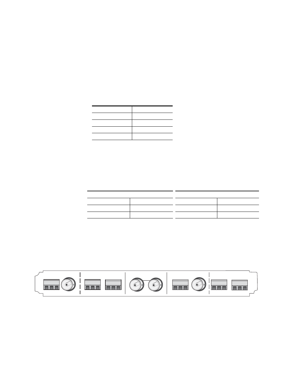
Figure 5. 2020ADC Input/Output Connectors
Table 1. Audio Input Connections
Audio Channel
Terminal Block
1 (Left)
J8, CH1 (L) IN
2 (Right)
J7, CH2 (R) IN
3 (Left)
J2, CH3 (L) IN
4 (Right)
J1, CH4 (R) IN
Table 2. Audio Output Connections
75 ohm Unbalanced Outputs
110 ohm Balanced Outputs
Audio Channel
BNC Connector
Audio Channel
Terminal Block
1/2
J9, CH1/2 OUT
1/2
J10, CH1/2 OUT
3/4
J3, CH3/4 OUT
3/4
J4, CH3/4 OUT
8024_02r1
2020
ADC
J10
J9
J8
J7
J6
J5
J4
J3
J2
J1
CH3 (L) IN
OUT
REF
CH4 (R) IN
CH3/4
G
–
+
G
–
+
G
–
+
G
–
+
G
–
+
G
–
+
CH1 (L) IN
CH2 (R) IN
OUT
CH1/2