Configuration, Local onboard module configuration – Grass Valley 2020ADC A-To-D User Manual
Page 16
16
2020ADC — Instruction Manual
Configuration
Configuration
The 2020ADC can be configured locally using on-board switches and
jumpers, or remotely using the 2000NET network interface. Configuration
and adjustment items for the 2020ADC include:
•
Input level (Ch 1 – Ch 4) – gain adjustment of analog input levels for
full-scale digital outputs,
•
Output mode – channel swapping, summing, and phase inversion, and
•
Control mode – Local/remote or local control only (remote lockout).
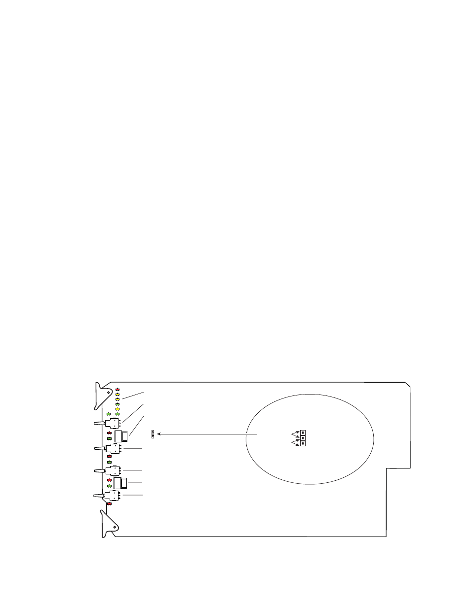
Local Onboard Module Configuration
The 2020ADC module can be configured locally using the jumper, the
rotary switches and four paddle switches shown in
. The CONF
LED indicates status of the configuration process.
These components perform the following:
•
Jumper JP2 sets control mode for Local only or Remote and Local.
•
Function (rotary) switches SW2 (CH1/2) and SW 5 (CH3/4) select the
desired output configuration (0 through 9, A through F). Either func-
tion switch position 0 or F (Factory defaults) can be used to return the
module configuration to the original factory default settings.
•
Paddle Switches (CH 1 – 4) adjust the gain of each analog audio input
channel for full-scale digital outputs.
•
CONF (configuring) LED, when on, indicates the module is initializing
or processing configuration information.
Figure 7. Module Configuration Switches and LEDs
8024_03r1
Remote Control Lockout
JP2
LOCAL
LOCAL & REM
Jumper across these pins
locks out remote control
Jumper across these pins
enables remote and
local control
SW2 – CH 1/2 Function Rotary Switch
SW5 – CH 3/4 Function Rotary Switch
SW4 – CH3 In Level
SW6 – CH4 In Level
SW1 – CH1 In Level
SW3 – CH2 In Level
1
CONF – configuration processing LED