Figure 11 – H3C Technologies H3C WX3000E Series Wireless Switches User Manual
Page 44
37
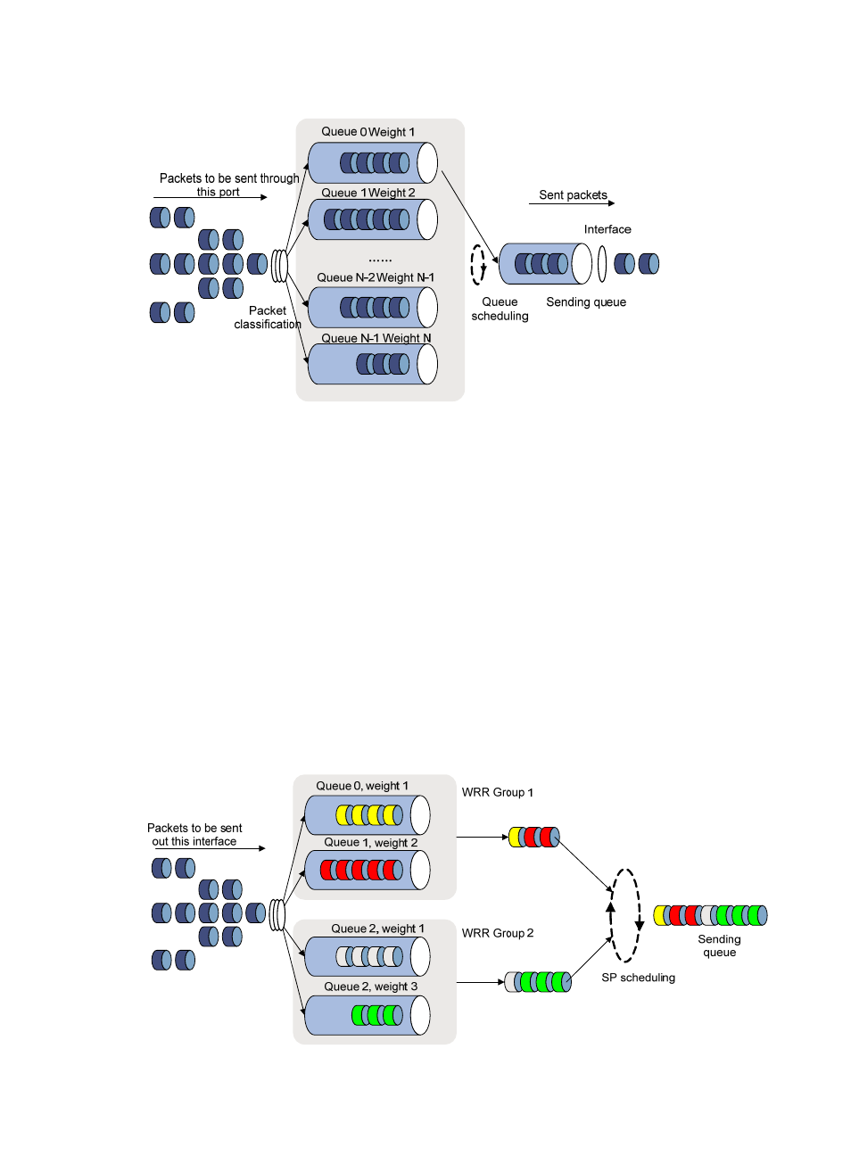
Figure 11 Schematic diagram for WRR queuing
Assume a port provides four output queues. WRR assigns each queue a weight value (represented by w3,
w2, w1, or w0) to decide the proportion of resources assigned to the queue. On a 100 Mbps port, you
can configure the weight values of WRR queuing to 50, 30, 10, and 10 (corresponding to w3, w2, w1,
and w0, respectively). In this way, the queue with the lowest priority can get a minimum of 20 Mbps of
bandwidth. WRR avoids the disadvantage of SP queuing that packets in low-priority queues may fail to
be served for a long time.
Another advantage of WRR queuing is that when the queues are scheduled in turn, the service time for
each queue is not fixed. If a queue is empty, the next queue will be scheduled immediately. This improves
bandwidth resource use efficiency.
The switching engine on a WX3000E wired-wireless switch supports group-based WRR queuing. You
can organize WRR queues into WRR scheduling groups 1 and 2. During queue scheduling, WRR is
performed in each group, and then the dequeued packets are scheduled by using SP queuing.
For example, assign queues 0 and 1 to WRR scheduling group 1, with the weight of 1 and 2, respectively;
assign queues 2 and 3 to WRR scheduling group 2, with the weight of 1 and 3, respectively. The
following figure shows how these queues are scheduled.
Figure 12 Queue scheduling for the two WRR scheduling groups