Ensemble Designs 5420 SD Logo Inserter User Manual
Page 8
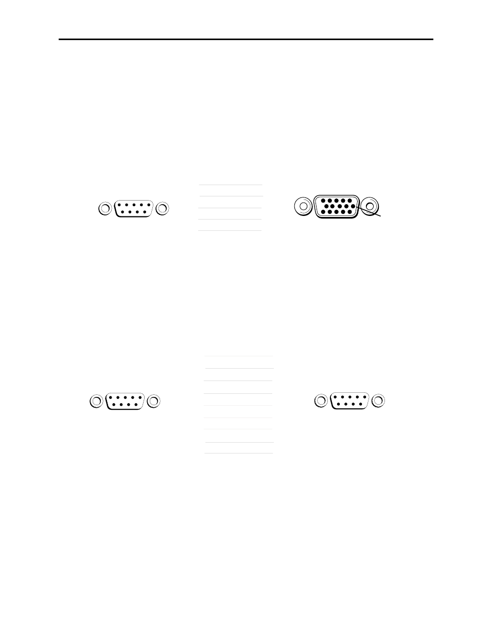
Avenue GPI Remote Control Panel
Connect an Avenue 5815 GPI Control Panel from the rear of the control panel (either
DB 9-pin male) to the Control connector on the rear of the 5420 module (HDB 15-pin
male). The pinout for this connecting cable is given below.
The 5815 GPI Control Panel can be rack-mounted in a standard 19 inch equipment
rack. Connect the universal in-line power supply provided to the connector at the left
rear of the GPI panel. The power supply is auto-sensing and requires no adjustments.
Up to eight Avenue 5815 GPI Control Panels can be connected in parallel for GPI
control. Panels are connected together via the DB 9-pin loop-through connectors on
each panel. The cable to connect each panel is a DB 9-pin male to DB 9-pin male with
straight pin-to-pin connections as shown in the illustration below. This cable may be
purchased at any electronics supply store or constructed from the diagram. Note not
all pins are necessary for control panel connection but all pins can be connected.
Model 5420 Digital Logo Inserter
Avenue GPI
Control Panel
DB-9 Male
5420 Control
Connector
HDB-15 Male
2
7
9
8
3
1
2
3
4
5
TX +
GND
RX +
RX –
TX –
Pin 1
Pin 1
Pin 11
Pin 6
Pin 6
Control
Avenue GPI Remote Control Panel to Avenue Frame Pinout
Avenue GPI
Control Panel
DB-9 Male
Avenue GPI
Control Panel
DB-9 Male
1
2
3
4
5
6
7
8
9
1
2
3
4
5
6
7
8
9
Pin 1
Pin 6
Pin 1
Pin 6
Only bolded pins are necessary
for control panel communication,
however, all pins may be connected.
Avenue GPI Remote Control Loop-through Pinout
5420-8