Eneo HDR-5004AH1.0 User Manual
Page 14
CH 1 Product Introduction
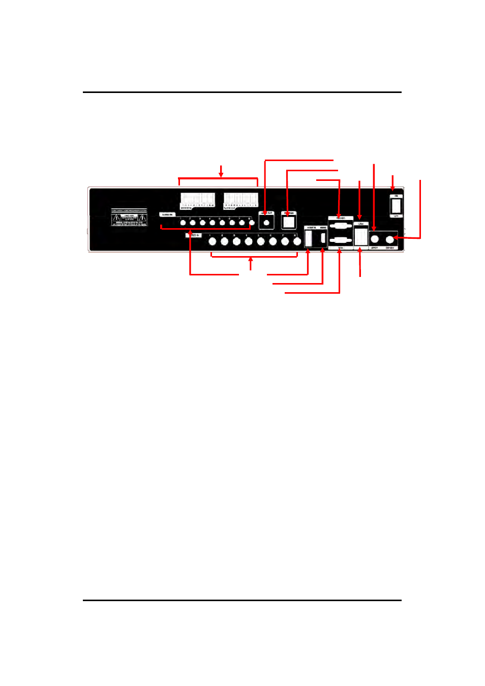
[Rear Panel]
14.Spot Out
4.Adapter
2.Audio Out
12. Sensor, Alarm, RS485
7. LAN
3. Switch
13. Extend
5. RS232C
1.Video In
6. e-SATA
11. VGA
10.HD Out
9. Audio In
8. USB
1. Video In
: This receives images from cameras and sends them to monitors.
Loop Out
: This sends the images from the cameras to the other devices.
2. Audio Out
:
RCA audio out terminal.
3. Power Switch
4. Adapter
: Connect DC12V only.
5. RS232C
: This is Serial communication(RS232C) cable connection terminal
5. RS232C
: This is Serial communication(RS232C) cable connection terminal.
6. e-SATA
7. LAN Port
: This is LAN cable connection terminal.
8. USB ports
: This USB port is for mouse and USB devices.
9. Audio In
: RCA audio in terminals. You can record 16 channels at the same
time.
10. HD Out
: Real HD(1920X1080) output for high resolution monitor
11 VGA port
: video output for VGA display
11. VGA port
: video output for VGA display
12. Sensor, Alarm, RS485
: For external sensor and external electric devices to
these terminal block. There are 16 inputs, 2 relay output and 14 TTL output.
For control the pan and tile cameras. Make sure that the polarity.
13. VGA Extend (option)
: Connect EXTEND FTP cable to Receiver
14. Spot Out
: For spot CRT monitor, composite signal comes out.
14
※
For more details, refer to [CH 2. Installation Method and Cautions].