Amer Networks SS2GD8IP User Manual
Page 27
Publication date: Dec., 2010
Revision B1
15
Sum up all elements’ bit-time delay and the overall bit-time delay of
wires/devices must be within Round Trip Delay (bit times) in a half-duplex network
segment (collision domain). For full-duplex operation, this will not be applied. You
may use the TP-Fiber module to extend the TP node distance over fiber optic and
provide the long haul connection.
• Typical Network Topology in Deployment
A hierarchical network with minimum levels of switch may reduce the timing
delay between server and client station. Basically, with this approach, it will
minimize the number of switches in any one path; will lower the possibility of
network loop and will improve network efficiency. If more than two switches are
connected in the same network, select one switch as Level 1 switch and connect all
other switches to it at Level 2. Server/Host is recommended to connect to the Level
1 switch. This is general if no VLAN or other special requirements are applied.
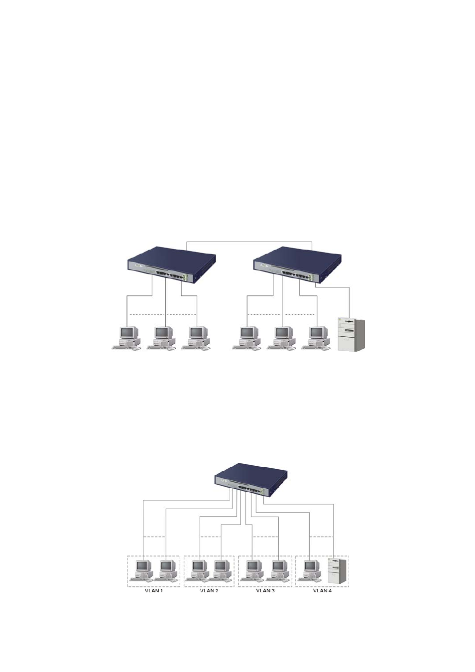
Case1: All switch ports are in the same local area network. Every port can access
each other (See Fig. 2-3).
If VLAN is enabled and configured, each node in the network that can
communicate each other directly is bounded in the same VLAN area.
Here VLAN area is defined by what VLAN you are using. The switch
supports both port-based VLAN and tag-based VLAN. They are different in practical
deployment, especially in physical location. The following diagram shows how it
works and what the difference they are.
Case2a: Port-based VLAN (See Fig.2-4).
Fig. 2-3 No VLAN Configuration Diagram
Fig. 2-4 Port-based VLAN Diagram