1-3-3. switch cascading in topology – Amer Networks SS2GD8IP User Manual
Page 26
Publication date:Dec., 2010
Revision B1
14
⎯
Gigabit Fiber with multi-mode LC SFP module
⎯
Gigabit Fiber with single-mode LC SFP module
⎯
Gigabit Fiber with BiDi LC 1310nm SFP module
⎯
Gigabit Fiber with BiDi LC 1550nm SFP module
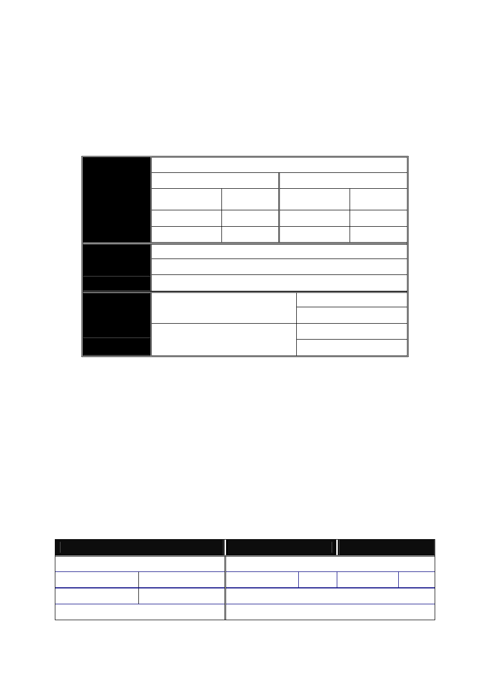
The following table lists the types of fiber that we support and those else not
listed here are available upon request.
Multi-mode Fiber Cable and Modal Bandwidth
Multi-mode 62.5/125
μm Multi-mode
50/125
μm
Modal
Bandwidth
Distance
Modal
Bandwidth
Distance
160MHz-Km
220m
400MHz-Km
500m
IEEE 802.3z
Gigabit Ethernet
1000SX 850nm
200MHz-Km
275m
500MHz-Km
550m
Single-mode Fiber 9/125
μm
Single-mode transceiver 1310nm 10Km, 30km, 50Km
1000Base-
LX/LHX/XD/ZX
Single-mode transceiver 1550nm 100Km
TX(Transmit) 1310nm
Single-Mode
*20Km
RX(Receive) 1550nm
TX(Transmit) 1550nm
1000Base-LX
Single Fiber
(BIDI LC)
Single-Mode
*20Km
RX(Receive) 1310nm
Table2-1
2-1-3-3. Switch Cascading in Topology
• Takes the Delay Time into Account
Theoretically, the switch partitions the collision domain for each port in switch
cascading that you may up-link the switches unlimitedly. In practice, the network
extension (cascading levels & overall diameter) must follow the constraint of the
IEEE 802.3/802.3u/802.3z and other 802.1 series protocol specifications, in which
the limitations are the timing requirement from physical signals defined by 802.3
series specification of Media Access Control (MAC) and PHY, and timer from some
OSI layer 2 protocols such as 802.1d, 802.1q, LACP and so on.
The fiber, TP cables and devices’ bit-time delay (round trip) are as follows:
1000Base-X TP, Fiber
100Base-TX TP
100Base-FX Fiber
Round trip Delay: 4096
Round trip Delay: 512
Cat. 5 TP Wire:
11.12/m
Cat. 5 TP Wire:
1.12/m
Fiber Cable:
1.0/m
Fiber Cable :
10.10/m
TP to fiber Converter: 56
Bit Time unit : 1ns (1sec./1000 Mega bit) Bit Time unit: 0.01
μs (1sec./100 Mega bit)
Table 2-2