Advance curve, Changing advance springs, Changing advance stop bushing – Allstar Performance ALL81220 User Manual
Page 3: Locking centrifugal advance
Allstar Performance 8300 Lane Drive, Watervliet MI 49098
Phone: (269) 463-8000 Fax: (800) 772-2618 www.allstarperformance.com
Advance Curve
The function of advance curve is to match ignition timing to the burning rate of fuel and rpm of engine. Ignition timing may need
to be changed if the burning rate of fuel or engine rpm is altered in any way. When selecting an advance curve, use as much initial
advance as possible without encountering excessive starter load or engine kick back. Start the centrifugal advance just above idle
rpm. The starting point of centrifugal advance curve is controlled by the installed length and tension of the spring.
Advance spring stiff ness controls the rate of the centrifugal advance slope. A lighter spring will provide a faster advance curve. Ad-
vance bushing size controls the amount of advance. A smaller bushing will produce a slower advance. The following factors will
aff ect engine timing.
Factor
Delay Timing
Advance Timing
Air & Fuel Mixture
Lean
Rich
Combustion Chamber Shape
Compact
Open
Combustion Turbulence
High
Low
Cylinder Pressure
High
Low
Octane Of Fuel
Low
High
Ignition Energy
High
Low
Load
Heavy
Light
RPM
Low
High
Spark Plug Location
Centered
Off set
Temperature
Hot
Cool
Vacuum
Low
High
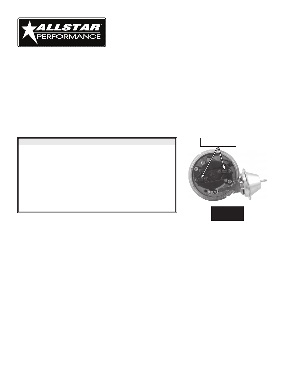
Changing Advance Springs
Remove distributor cap and rotor. Remove springs from spring posts using a pair of needle nose pliers. Install new springs with
needle nose pliers, reattach rotor, reattach cap.
See Figure 3.
Changing Advance Stop Bushing
Remove distributor cap and rotor. Remove locknut and washer on bottom of advance assembly. Remove existing bushing and
replace with new bushing. Install washer, tighten locknut, reattach rotor, reattach cap.
See Figure 4 on the next page.
Locking Centrifugal Advance
Remove advance springs, weights, and advance stop bushing - a small locknut with nylon insert and washer holds the advance
stop bushing in place. Next remove roll-pin from the drive gear and remove the gear from shaft. While sliding the shaft out of the
housing, approximately 2 ½ inches, rotate the shaft 180 degrees and insert the advance stop bushing pin into the hole of advance
plate. Reattach the washer and locknut to the advance stop bushing pin. Reinstall the drive gear and roll pin.
See Figure 4 on the
next page.
Advance Springs
FIG. 3
FORM 1031
Page 3 of 4
Rev.071907