Allstar Performance ALL10300-40 User Manual
Round tubing bender, Operation manual
Allstar Performance 8300 Lane Dr., Watervliet, MI 49098
Phone: (269) 463-8000 Fax: (800) 772-2618 www.allstarperformance.com
Form 1059
Page 1 of 3
Rev. 082012
Round Tubing Bender
opeRaTion manual
SpeCiFiCaTionS:
maximum Tubing Thickness
Bend up To .134" Wall Thickness
Hydraulic
Jack
8-Ton
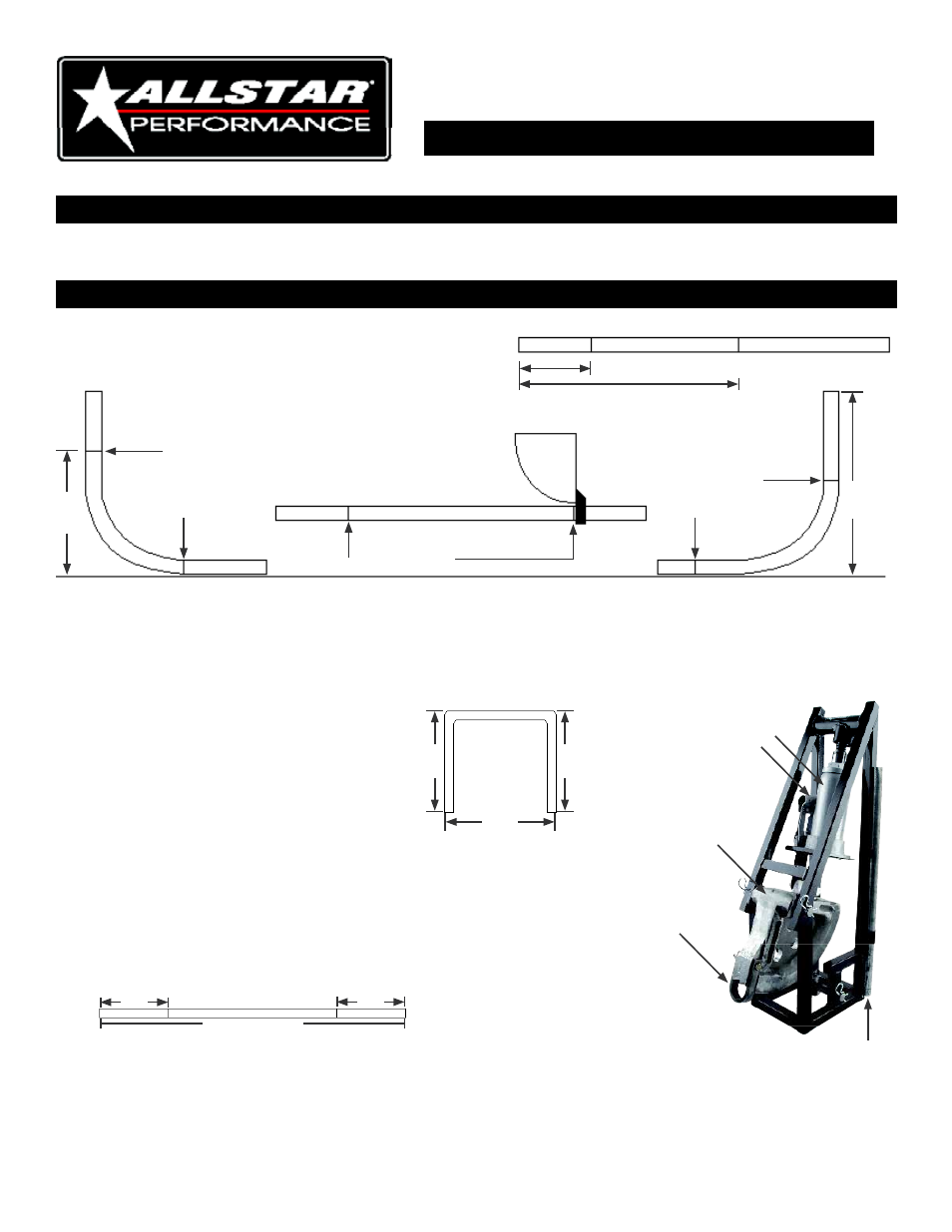
BenDinG TuBinG:
When tubing is bent one side gets longer, the other gets shorter. To determine this, make a mark 10" from the end of
the pipe, and another mark 30" from the same end.
•
Make a 90-degree bend then lay the bent pipe on a flat surface to measure the distance (X) to the top. This number minus 10"
will be the nose length.
•
Lay the pipe with the other end up and measure the distance to the 30" mark. Twenty inches minus this distance will be the tail
length.
•
If using a 1-3/4" die shoe, the nose should be about 12" and the tail should be about 5-3/4". Note: Every pipe diameter will yield
different results.
10"
30"
30"
10"
30"
Die
Shoe
10" mark
30"
10"
install tubing into bender with 10" mark at the nose.
X
•
To find the length of tubing needed to make a hoop,
use the following formula:
2 times height + width + 2 times tail - 2 times nose.
Example - A 40" high by 48" wide hoop as follows:
A.) 2 x 40" + 48" + 2 x 5-3/4" - 2 x 12" = 115-1/2"
B.) 80 + 48" + 11-1/2" - 24" = 115-1/2"
•
Mark the first bend at 40" - 12" (nose) = 28". This mark should
line up on the front of the bender, same as 10" previous mark
previously.
•
Bend 90-degree - Turn pipe around to other mark. Bend
other end up.
28"
28"
115-1/2"
40"
40"
48"
a
B
C
D
e
a. Hydraulic Jack
(Sold Separately)
B. Jack Handle Sleeve
C. Die Shoe
D. nose Strap
e. Jack Handle
Shown With Jack Installed