Allstar Performance ALL11350 User Manual
Page 2
Allstar Performance 8300 Lane Dr., Watervliet, MI 49098
Phone: (269) 463-8000 Fax: (800) 772-2618 www.allstarperformance.com
Form 1142
Page 2 of 2
Rev. 011315
Removal Continued:
1.
Place removal mandrel through fixture with ball end towards bell and start mandrel nut on ball end.
2.
Thread nut down mandrel and position into hex in fixture head.
3.
Apply a generous amount of high pressure grease to ball end and threads of removal mandrel.
4.
Tighten removal mandrel until ball is seated inside outer removal slug (See Figure #3) .
5.
Using a torque wrench set at 200ft pounds tighten mandrel and press out old tube. If 200ft pounds
is reached and tube has not begun to move it will be necessary to heat the bell around the area
where the tube is installed with a heat gun. Do not attempt to heat
bell with an open flame such as cutting torch.
6.
Tighten mandrel until tube is fully removed.
Installing Axle Tubes:
1.
Place bearing assembly over installation mandrel.
2.
Place end cap over installation mandrel with stepped end away from
bearing, this will contact end of axle tube when pressing assembly together.
3.
Install installation mandrel in snout end of tube (See Figure #4).
4.
Install installation mandrel in bell as it would be assembled.
5.
Place bell support cone over installation mandrel with wide end towards bell.
6.
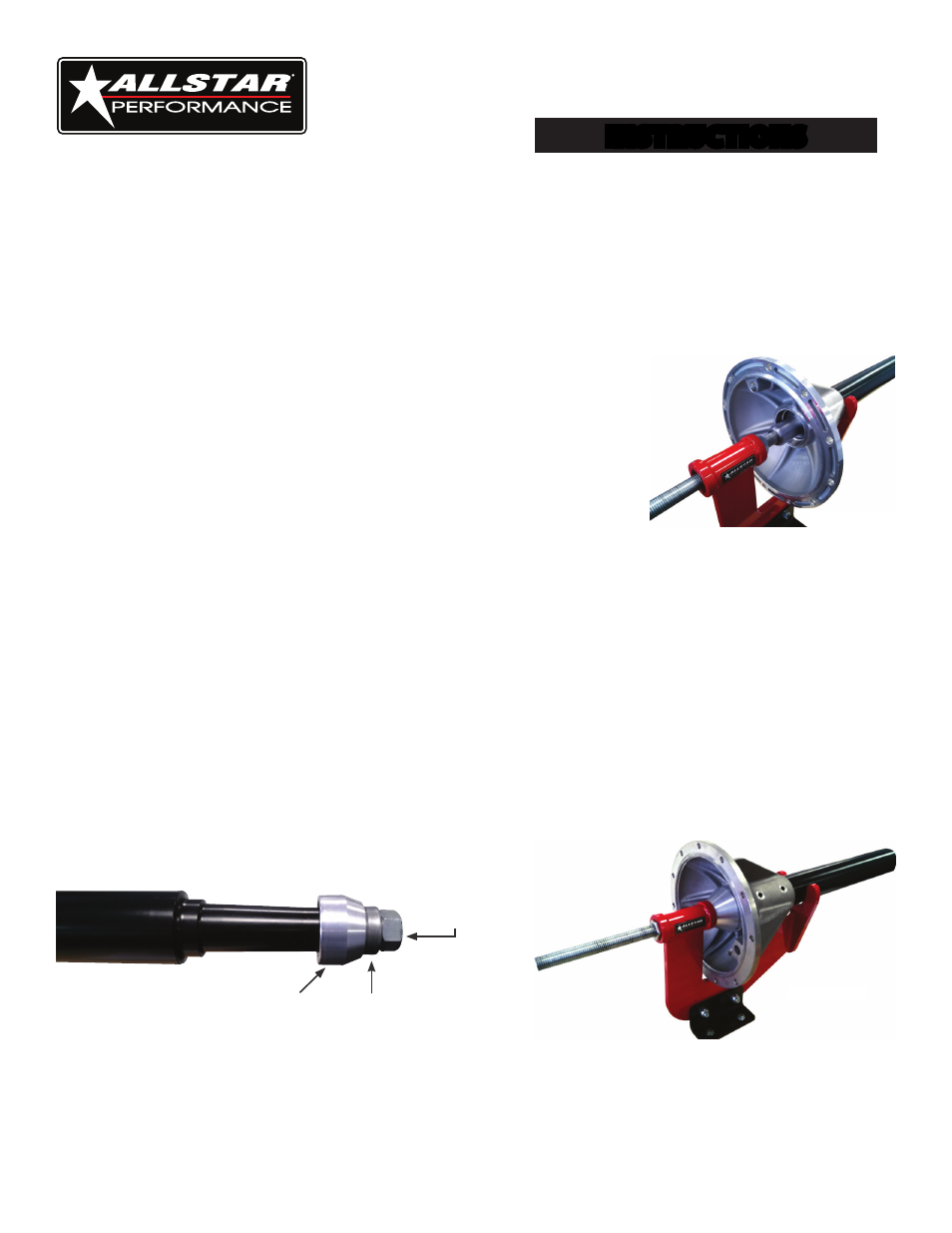
Place tube and bell assembly in fixture as shown in Figure #5.
7.
Apply a generous amount of high pressure lube to threaded end of assembly mandrel.
8.
Place installation mandrel through fixture.
9.
Thread nut onto mandrel and position into hex in fixture head.
10.
Apply penetrating oil or similar lubricant to inside of bell and outside of tube to assist assembly.
11.
Tighten mandrel keeping axle tube and bell straight until tube seats into bell. Note: Due to the
varying tolerances of tubes and bells it may be required to chamfer the end of the tube to assist in
starting tube into bell.
INSTRUCTIONS
Quick Change Tube
Install/Removal Tool
Figure #4
Installation
Mandrel Bearing
Installation
Mandrel
End Cap
Figure #3
Figure #5