Operation – Allmand Brothers NL PRO II User Manual
Page 46
46
OPERATION
OPERATION
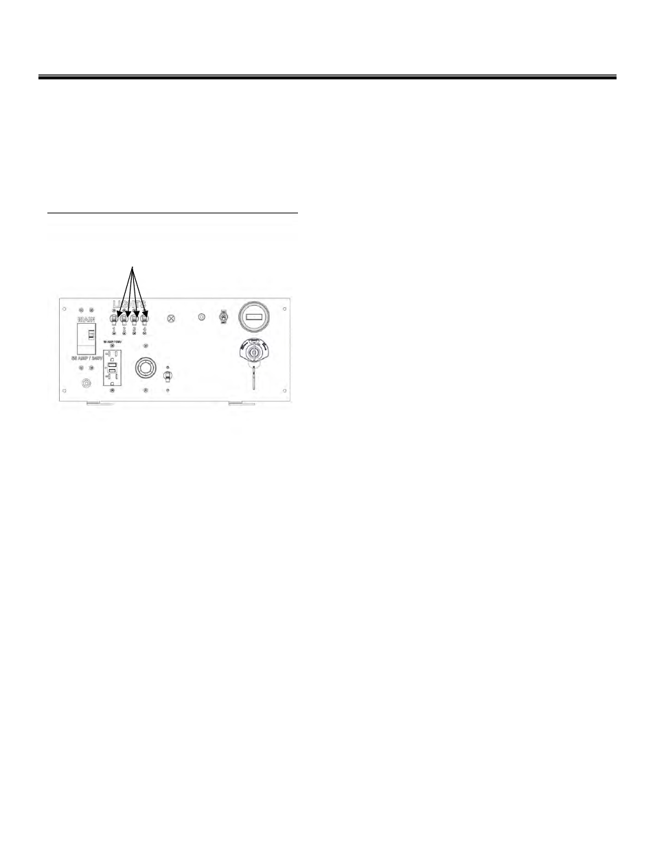
Light Control Panel
The tower light control panel contains the
breaker switches.
The four light fixtures are controlled and pro-
tected by four breaker switches located on the
light control panel.
SHUTDOWN PROCEDURE
Shutdown - Short period
When shutting down the light tower for a short
period, perform the following procedures.
1. With the lights off, lower the light tower to the
full DOWN position; see Raising and Lowering
the Light Tower on page 43-44.
2. Turn the engine off. Refer to your Engine Op-
erator’s Manual for stopping procedure.
Shutdown - Long - Term or Prepare for Trail-
ering
When shutting down the light tower for long peri-
ods of time or when preparing to trailer; see Long
- Term Storage section on page 52 or Shutdown -
Prepare for Trailering section on page 18.
AUXILIARY AC OUTLET OPERATION
Depending on model options, the 240VAC 1 -
phase control panel is equipped with one
240VAC outlet and one 110VAC GFCI outlet for
powering accessories from the generator. Power
is supplied to the outlets only when the engine /
generator is running and the main circuit breaker
is in the ON position.
The 240VAC outlet is protected by a 30A circuit
breaker.
The 110VAC GFCI outlet is protected by a 20A
push button type circuit breaker.
The main circuit breaker is a 35A DPST circuit
breaker.
If any of the outlet circuit breakers trip, switch off
the lights, remove the load to the outlets and wait
10 minutes for the bulbs to cool before turning
them back on.
1. Disconnect the load from the outlet.
1
Figure 20
1. Light Breaker Switches.
Lights On
Before turning the lights on, the engine must
be running and should be allowed to reach
normal operating temperature.
Turn one or more light breaker switches to the
ON position.
Lights Off
Turn all light breaker switches to the OFF po-
sition.