Gear and pump assembly, Replacement of electrical components – AIRLESSCO LP500 User Manual
Page 15
Maintenance
3A1185H
15
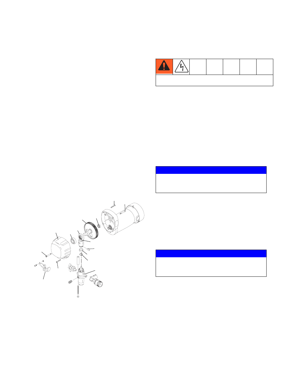
Gear and Pump Assembly
Servicing Gear box Assembly
1. Remove fluid pump. See Fluid Pump Disconnect,
page 12.
2. Remove frame from the gearbox by loosening the
four mounting screws.
3. Separate cover assembly (13) from box by remov-
ing bolts (1) from front of cover and back of box and
shoulder bolts (2) from front of cover and back of
box.
4. Lay unit on its back and disassemble gearbox.
5. Inspect bearings (14, 17), Crosshead Assembly
(15), Gearcrank (16) and sleeve bearing (10) inside
cover assembly (15) for wear/damage. Replace
worn/damaged parts.
6. If gear grease needs replacing, replace with gear
grease (Part No. 114819).
7. Clean mating surfaces of cover and box thoroughly.
Apply Loctite
®
518 on half the bottom surface of end
bell.
8. Reassemble in reverse order.
Replacement of Electrical
Components
NOTE: Anytime the pressure control assembly, sensor,
or both are replaced, perform the calibrations.
Pressure Control Assembly (Electrical
Control Board)
1. Unplug machine’s power cord.
2. Remove six screws heatsink housing.
3. Disconnect all leads from pressure control assem-
bly.
4. Reassemble in reverse order.
Sensor
1. Remove the four screws, heatsink, and lower the
pressure control assembly.
2. Disconnect sensor lead from the board.
3. Unscrew sensor by holding sensor with 3/4” wrench.
4. Reassemble in reverse order.
Potentiometer
1. Lower pressure control assembly as described
above.
2. Disconnect potentiometer lead from pressure con-
trol assembly.
3. Use a 1/16” allen wrench, loosen set screw in the
poteniometer knob and remove knob and spacer.
4. Using a 1/2” wrench or deep socket, remove the nut
from the potentiometer shaft assembly.
ti22326a
1
12
2
13
15
11
14
17
1
16
2
6
4
5
8
10
Always unplug the electrical cord before servicing the
machine.
NOTICE
Unit will not operate if wires are disconnected or
pinched. Upon reassembly, ensure all wires are
connected and not pinched.
NOTICE
Unit will not operate if wires are disconnected or
pinched. Upon reassembly, ensure all wires are
connected and not pinched.