System diagram, Grid view – ACTi Floor Planner V2.3.2 User Manual
Page 20
ACTi Floor Planner User’s Manual
System Diagram
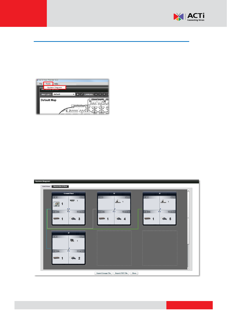
Once you have completed the relation setting, go to Tools System Diagram to see the
network system layout. There are two modes available. One is the Hierarchical View, the other
is the Grid View.
Grid View
Grid View displays all the elements according to the map they are located in. The camera and
switch are shown in the lower half of each cell, while the CMS server and NVR server are on
the top of each cell. The lines in the middle of each map connect the camera to the switch, the
NVR server to the switch, and the CMS server to the switch. And the lines out of each cell
connect the map to the map. You may click and drag the map to another grid location, so that
the wires will be less tangled.