4 ss7 serial interface ports (spci2s), Ss7 serial interface ports (spci2s), Figure 3 – Welltech SPCI2S Boards User Manual
Page 32: Spci2s connector positions, Table 3, Pcm interface ports connector pin-out
Section 6 Interfaces
32
The connectors are 8-way RJ45, and are labeled L1 to L4 in
and on the product (L3 and L4 only for SPCI2S in
connector pin out and signal descriptions are shown in
. Note
that pin 1 is towards the top of the board for each RJ45 connector.
Table 3.
PCM Interface Ports Connector Pin-Out
Pin No
Direction
Function
1 Input
Receive
2 Input
Receive
3 N/C
4 Output
Transmit
5 Output
Transmit
6 N/C
7 N/C
8 N/C
6.4
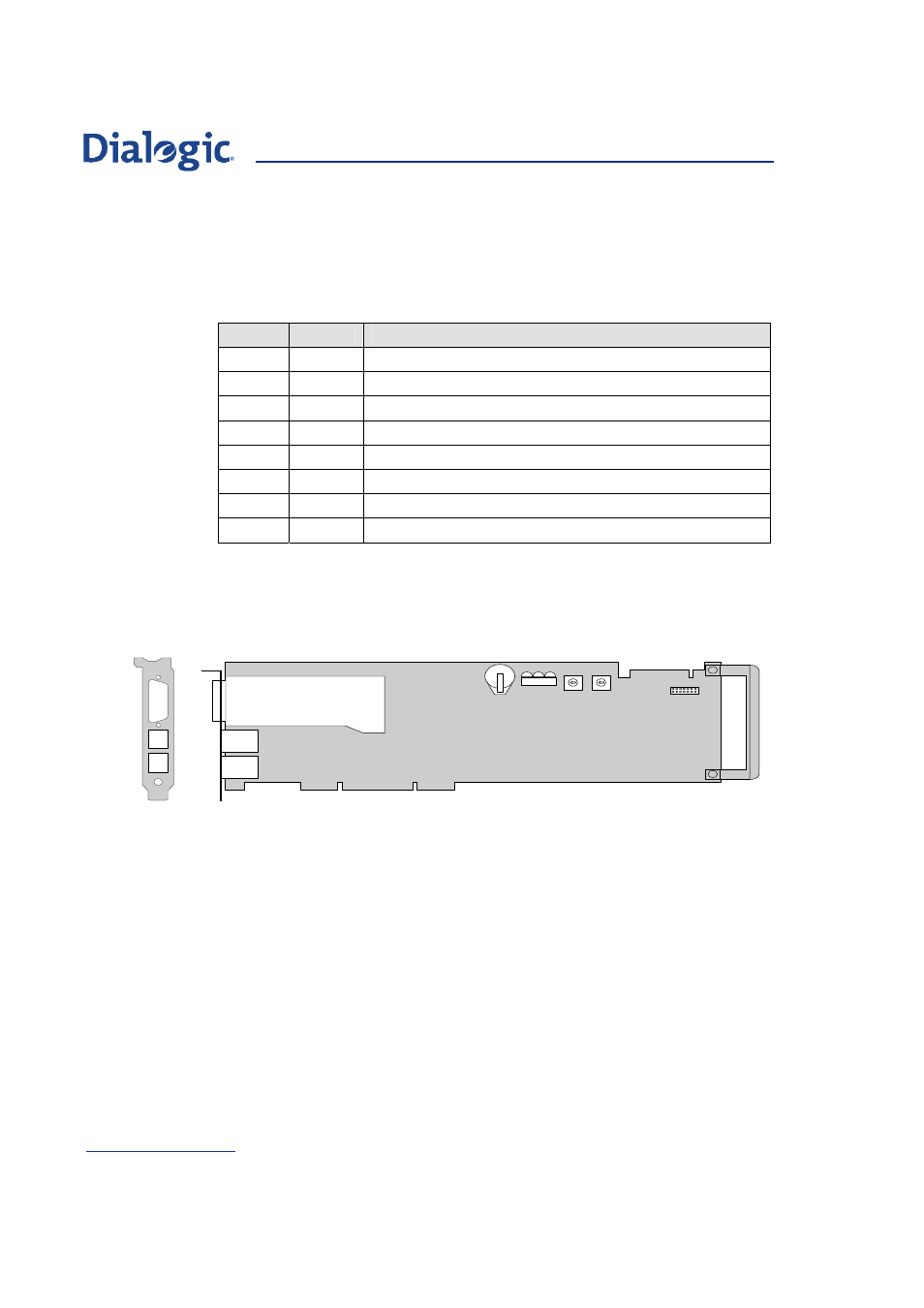
SS7 Serial Interface Ports (SPCI2S)
Figure 3.
SPCI2S Connector Positions
Each SPCI2S board provides two synchronous SS7 Serial Interface Ports.
Both ports are presented in a single 26 way female high density D-type
connector, and use V.11 (V.35 compatible) electrical interface characteristics.
The connector is labeled AUX in
and on the product. The
connector pin-out and signal assignment is shown in
which identifies the ports as A and B.
The SS7 Serial Interface Ports on the SPCI2S board are designated as SELV.
Install the ferrite clamp, provided with this product, on the SS7 Serial
Interface Port cable, close to the connector backshell, to ensure the EMC
performance of the product.
The SS7 Serial Interface Port may be clocked either by an internally
generated clock or by an externally applied clock. In both cases the same
clock is used for both the Transmit data and the Receive data.
For internal clock operation use the Transmit clock pins and make no
connection to the Receive clock pins on the D-type connector. For external
clock operation connect the clock source to the Receive clock pins on the D-
type connector and make no connection to the Transmit clock pins.
A U X
(V .1 1 )
L 3
L 4
A D D R
B O O T
J 3
L ic e n c e
B u tto n
U s e r
L E D s
V .1 1 S e ria l In te rfa c e
B o a r d
H .1 0 0
C o n n e c to r
C B A
C L K T E R M