6 interfaces, 1 user leds, 2 h.100 ct bus – Welltech SPCI2S Boards User Manual
Page 31: 3 pcm interface ports, Interfaces, User leds, H.100 ct bus, Pcm interface ports, Figure 2, Spci4 connector positions
Dialogic
®
SPCI2S and SPCI4 Boards User Manual Issue 7
31
6 Interfaces
This section details the interfaces present on the Dialogic
®
SPCI2S and SPCI4
products.
6.1 User
LEDs
Three general purpose red LEDs, labeled A, B and C, are available to the user
application.
Use of these LEDs is detailed in the
Dialogic
®
SS7 Boards Programmer’s
Manual for SPCI2S and SPCI4
.
6.2
H.100 CT Bus
An H.100 CT Bus interface is provided to allow connection to other H.100
compatible boards. The H.100 CT Bus supports 4096 channels (or timeslots)
and the associated clock and framing signals. This board is capable of
generating the CT Bus clocks, or can act as a slave. CT Bus channels may be
used individually, or grouped to provide a higher bandwidth data path.
The signals are carried between boards in a host computer using an H.100 CT
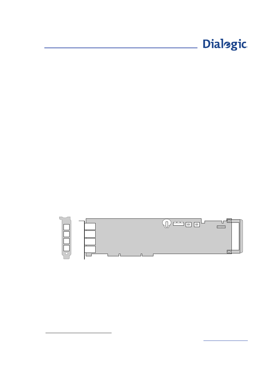
Bus ribbon cable. The position of the H.100 connector can be seen in
6.3
PCM Interface Ports
Figure 2.
SPCI4 Connector Positions
Each board provides two (SPCI2S) or four (SPCI4) primary rate
telecommunications (PCM) interfaces, each port being individually configured
at run-time under software control to operate as balanced E1, T1 or J1 ports,
with selectable line code and frame format. For information on setting port
configurations consult the SS7 Boards Programmer’s Manual for SPCI2S and
SPCI4
∗
.
The E1/T1/J1 ports on the boards are Safety Extra Low Voltage, SELV – the
apparatus connects to the outside network via network termination units
(NT1).
Use twisted-pair, screened cables, grounded at both ends, to ensure the EMC
and error-free performance of the product.
∗
Document number U03HSP.
A D D R
B O O T
J 3
L ic e n c e
B u tto n
U s e r
L E D s
H .1 0 0
C o n n e c to r
C B A
C L K T E R M
L 1
L 3
L 4
L 2