4 host specific installation aspects, 5 switch and link settings, 6 software license button – Welltech SPCI2S Boards User Manual
Page 28: Host specific installation aspects, Switch and link settings, Software license button, Table 2, License button symbols
Section 5 Hardware Installation
5.4
Host Specific Installation Aspects
The instructions that follow provide all of the installation information specific
to the board. Any information relating to the host computer will, of necessity,
be general in nature. Always consult the documentation provided with the
host for more details of these aspects.
If the board is being installed in a Dialogic
®
SS7G21 product, either as an
upgrade or a repair, then the relevant Hardware Manual provides full
instructions
, and should be used in preference to the remainder of
Section
.
5.5
Switch and Link Settings
The two switches, labeled ADDR (SW1) and BOOT (SW2), are set to 0 for
normal operation. Alternative modes are detailed in the SS7 Boards
Programmer’s Manual for SPCI2S and SPCI4
∗
.
Boards at each end of the H.100 CT Bus must terminate the clock lines; this
is achieved by fitting links (jumpers) at all 7 positions on the link field labeled
CLK TERM (J3). For boards in a ‘middle’ (non-end) position, the links
(jumpers) should be installed in an offset (open) state.
All other link positions are for manufacturing purposes only and should not be
fitted.
5.6
Software License Button
All software running on the board is enabled by a removable software license
button. This is a small metal can that resembles a battery and is fitted to a
holder near the top of the board.
Prior to installing the board the correct license button must be fitted. The
license button is supplied in a separate package. Carefully insert it into the
holder by sliding it under the clip. Ensure that both contacts of the holder
make good contact with the license button.
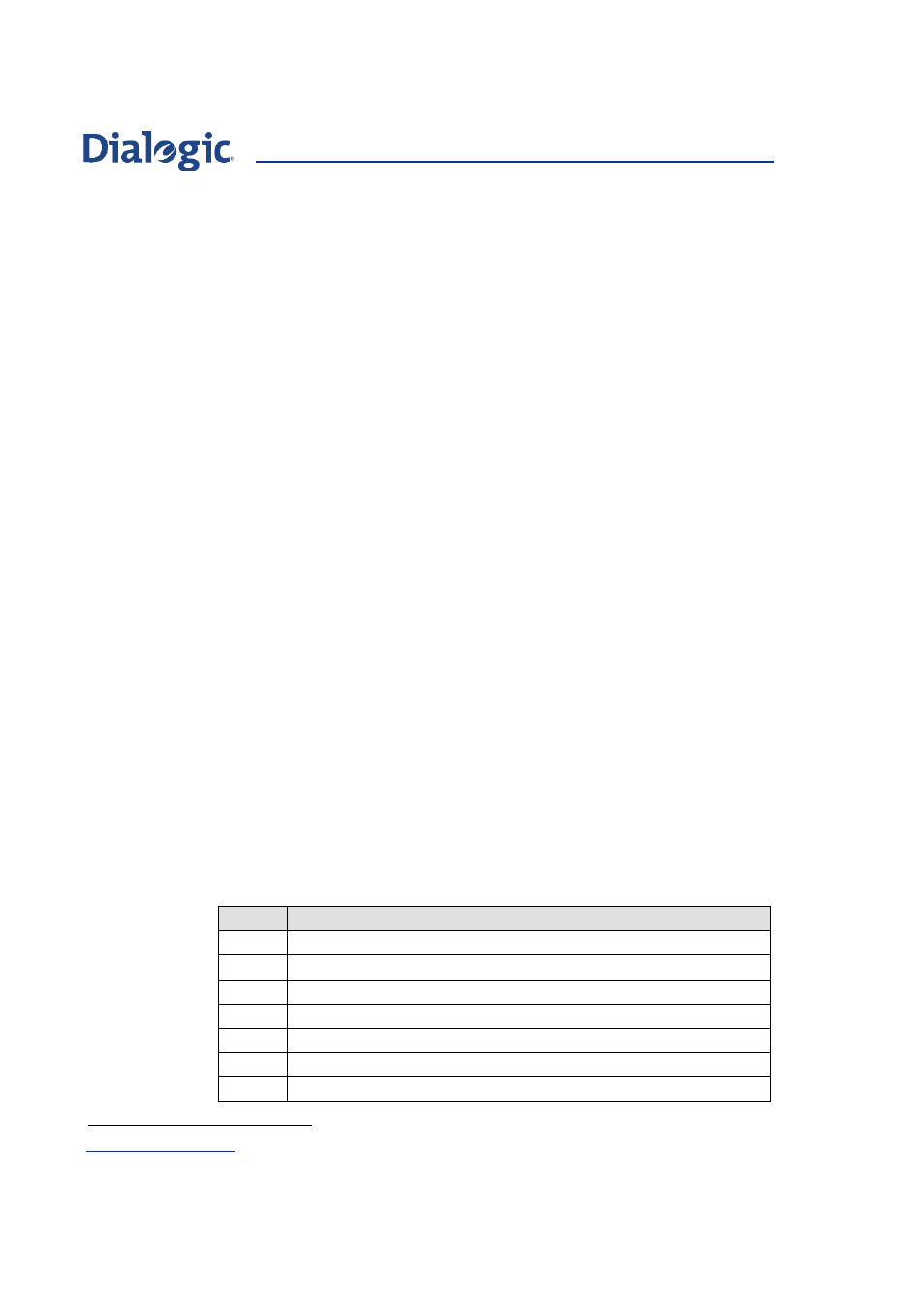
The software enabled by the license button is indicated by a symbol engraved
in the top of the button casing, as listed in
. For Product ID
(ordering codes) for license buttons refer to
Section 7
.
Table 2.
License Button Symbols
Symbol
Description
M2 MTP2
only
M3
MTP (MTP2 and MTP3)
T1
ISUP, TUP, MTP (Small)
T2
ISUP, TUP, MTP (Regular)
T4
ISUP, TUP, MTP (Large)
XX
For use in SS7G21, SIU520, SG430 systems only
MM
Multi-link MONITOR only
∗
U03HSP – Dialogic
®
SS7 Boards Programmer’s Manual for SPCI2S and SPCI4
28