Commlink ii wiring & cabling connections, Component & system wiring 45, Commlink ii wiring – WattMaster VAV User Manual
Page 45: Commlink jumper switch settings
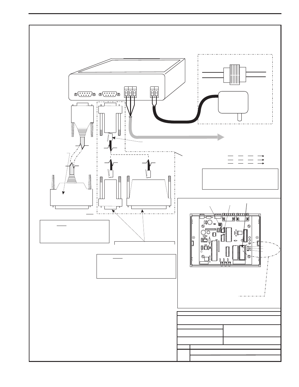
Component & System Wiring
45
Connect To Remote Link
.
Remote Link Is Part # OE419-04
Only
Commlink II Communications Interface
(Jumper Set For Multiple Loop)
Caution:
Use The “Molded Cable” To
Connect To The Computer (DCE) Connector.
This Cable Is Only To Be Used To Connect
From The CommLink (DTE) Connection To The
Remote Link (When Used).
Do Not
Caution:
Disconnect All Communication Loop Wiring
From The CommLink Before Removing Power
From The CommLink. Reconnect Power And Then
Reconnect Communication Loop Wiring.
Use 25 Pin Or 9 Pin Connector As
Required By Available Serial (COM) Port
On Computer.
JOB NAME
Caution:
Use The “25 Pin Or 9 Pin Cable” To
Connect To The Remote Link (DTE) Connector. This
Cable Is Only To Be Used To Connect From The
CommLink (DCE) Connection To The Computer
Serial Port (COM) Connection.
Do Not
(When Used)
Note:
Place Jumper Between
Pins 1 & 2 for Multiple
Loop Applications &
Between Pins 2 & 3 for
Single Loop Applications
See Note 4.
COMM DRIVER CHIP
( U1 )
EPROM CHIP
PIN 1
MULTI
SINGLE
1
2
3
CommLink Jumper Switch Settings
4 Piece Computer
Cable Kit.
Part # HZ000112
Supplied With
CommLink
FILENAME
B. CREWS
DESCRIPTION:
PAGE
DRAWN BY:
CommLink II Wiring
1
02/11/04
G-CommLinkWire.CDR
OE361-04
Notes:
DATE:
R
SH
T
R
SH
T
R
SH
T
R
SH
T
All Communication Loop
Wiring Is Straight Through
Connect To First Device On Loop. See
System Application Documentation For
Your Specific Systems Controller
Connection & Wiring Information
RS-485
19200 Baud
Line Voltage
See Note 1
24VAC
Required VA For Transformer
CommLink = 14VA Max.
CommLink Is Supplied With 110/24VAC Power Supply.
If Desired A Transformer (By Others)
May Be Wired To The CommLink Instead
Molded Modem Cable.
Part #HZ000098
Supplied With CommLink
(DTE)
REMOTE LINK
REMOTE LINK
485 LOOP
485 LOOP
COMPUTER
(DCE)
G
T
R
G
2
V
4
D
N
POWER
9P
in
Female
9 Pin
Female
25 Pin
Female
9P
in
Female
120/24 Vac
Transformer
Part # PX000015
25 Pin
Male
Part #OE361-04
Connect Supplied RJ12 Modular Phone Cable
To Supplied 9 Pin Or 25 Pin Connector As Reqd
By Your Computer Com Port Connection
1.)24 VAC Must Be Connected So
That All Ground Wires Remain
Common.
2.)All Wiring To Be In Accordance
With Local And National Electrical
Codes And Specifications.
3.)All Communication Wiring To Be
2 Conductor Twisted Pair With
Shield. Use Belden #82760 Or
Equivalent.
4.)CommLink Is Usually Shipped With The
Jumper In The Multiple Loop
Configuration. Check The Application
Documentation For Your Specific System
For Correct Jumper Position Setting.
CommLink II Wiring & Cabling Connections