Supply fan vfd wiring, Component & system wiring 25 – WattMaster VAV User Manual
Page 25
Component & System Wiring
25
Notes:
1.)All Wiring To Be In Accordance With
Local And National Electrical Codes
and Specifications.
FILENAME
DATE:
B. Crews
DESCRIPTION:
PAGE
DRAWN BY:
WMVAV Controller Wiring
JOB NAME
03/24/04
VAV-SupplyVFDWR1.CDR
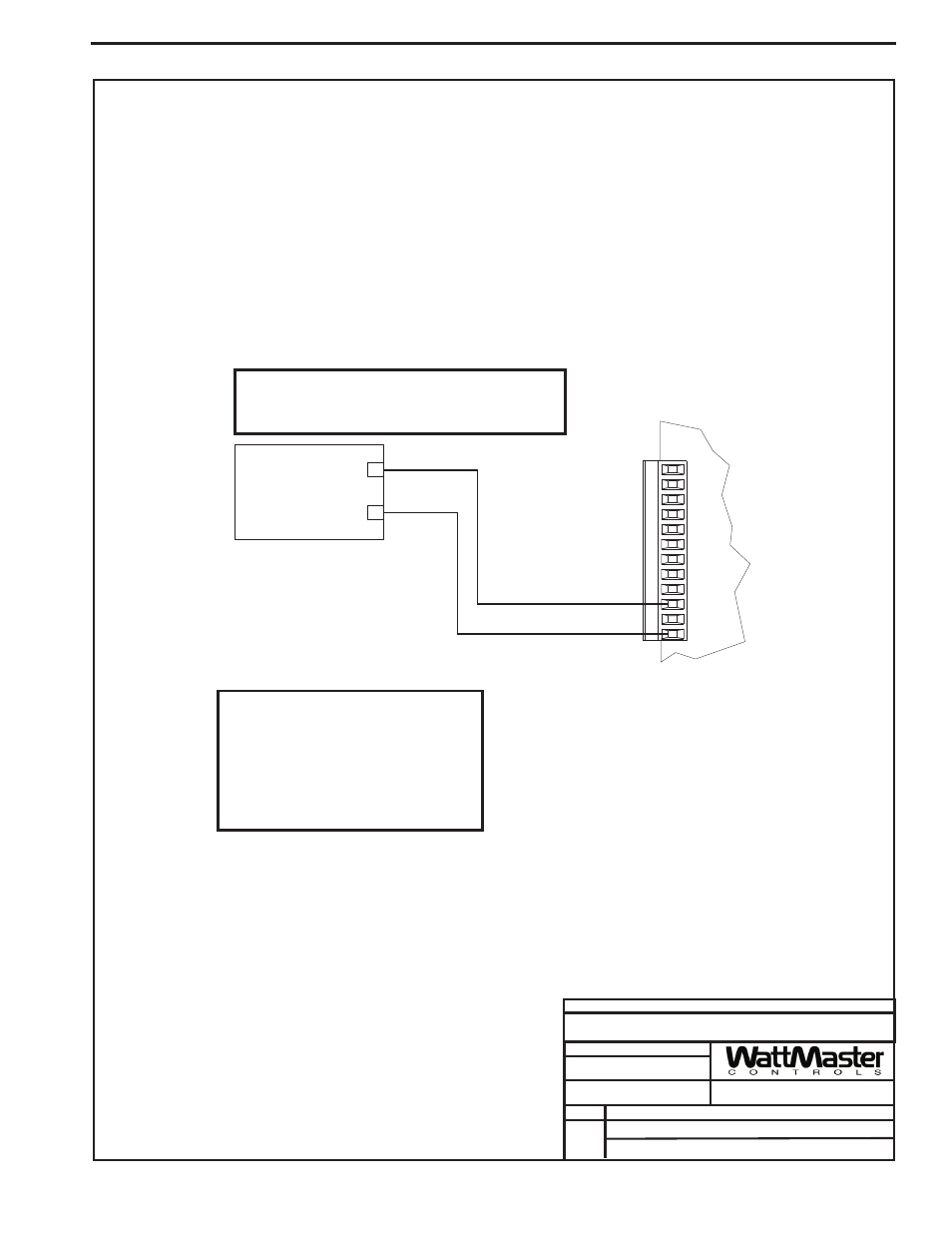
Supply Fan VFD To
1
+
Supply Fan
Variable Frequency Drive
(By Others)
_
VFD 0-10VDC Input
GND
The VFD Unit Must Be Configured For 0-10VDC Input. The
Input Resistance At The VFD Must Not Be Less Than 1000
Ohms When Measured At The VFD Terminals With All
Input Wires Removed.
GND
INPUTS
GND
AOUT1
AOUT2
GND
+VDC
AIN1
AIN2
AIN3
AIN4
AIN5
AIN7
WMVAV Unit Controller Board
Caution:
Variable Frequency Drive Units Can Cause Large
Transient Noise Spikes Which Can Cause
Interference To Be Propagated On Other
Electronic Equipment. Use Shielded Wire
Wherever Possible And Route All
Sensor/controller Wiring Away From The Variable
Frequency Drive And The Air Handling Unit
Electrical Wiring.
Supply Fan VFD Wiring