Diagnostics, Figure 2-3.b, V -v – Extron Electronics Matrix 6400 Series User Manual
Page 18
Extron • Matrix 3200/6400 Series • User’s Manual
Chapter 2 • Installing the Matrix 3200/6400 Video Switcher
AN
AH
EIM
, C
A
MA
DE
IN
US
A
AC P
OW
ER IN
PU
T
FUS
E: 2
50V
5
.0A
TT
100-240V 0.5A MAX 50/60Hz
DISCONNECT PO
WER CORD BEFORE SER
VICING
BM
E
AD
DR
ES
S
4
4
BME
ADDRESS
IN
OU
T
BME COMM.
MKP COMM.
A
B
C
D
E
A
B
C
D
E
Male
Connector
1
5
6
9
Item 1
Item 5
Item 3
Item 2
Item 4
IN
1 - 8
IN
9 - 1
6
17 -
24
25 -
32
33 -
40
41 -
48
49 -
56
57 -
64
INP
UTS
OU
TPU
TS
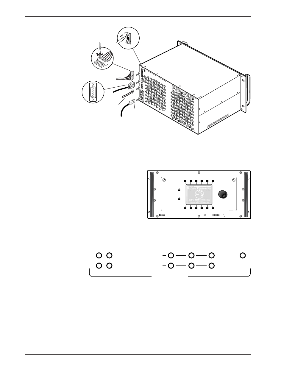
Figure 2-3.A Matrix 3200/6400 Video Switcher Connections (BME#0 only)
7A. BME Power-Up Verification
The Diagnostics LEDs shown in Figure 2-3.B are located on the front panel of the
Matrix 3200/6400 Video BME. The normal state of the LEDs after power-up is
Primary +V and -V LEDs ON. If the BME includes a Redundant power supply, the
Redundant +V and -V LEDs
will also be ON. If the
Primary power supply fails,
its LEDs will be OFF and
the Redundant LEDs will
blink.
The System Status LED will
initially blink indicating that
internal housekeeping is
occurring, when it goes
solid ON, the system is
ready.
2-3
POWER SUPPLIES
COMMUNICATIONS
PRIMARY
TX
RS232
BME
REMOTE
SYSTEM
STATUS
REDUNDANT
RX
DIAGNOSTICS
+V
-V
MATRIX 6400
VIDEO
POWER SUPPLIES
COMMUNICATIONS
PRIMARY
TX
RS232
BME
REMOTE
SYSTEM
STATUS
REDUNDANT
RX
DIAGNOSTICS
+V
-V
FPC-1000
RGB
MUTE
AUDIO
MUTE
Figure 2-3.B