9 user parameter data – Watson-Marlow Qdos30 User Manual
Page 33
Watson-Marlow qdos30 PROFIBUS Pump User Manual
33
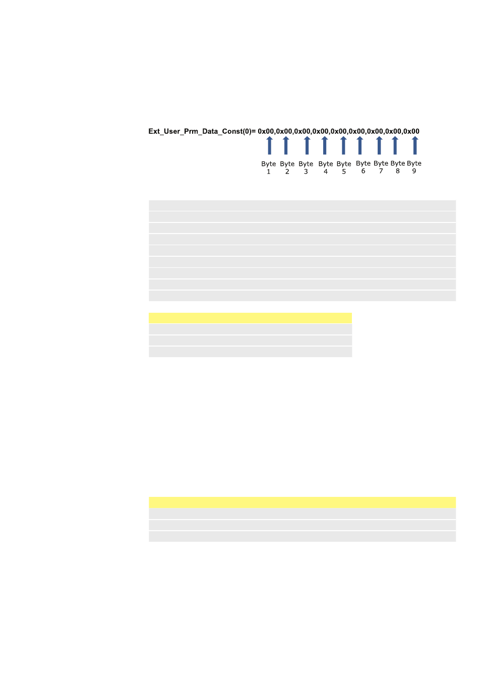
14.9 User Parameter Data
The user parameter data is set by entering values into the ‘Ext_User_Prm_Data_
Const(0)’ line of the GSD file. This is indicated below and the relevant bytes are
listed in the table. No further changes should be made to the GSD file and Watson-
Marlow accepts no responsibility for pump failures arising from changes to the GSD
file.
8 bit
Byte 1
Pump Model
8 bit
Byte 2
Head Type
8 bit
Byte 3
Min Speed (High byte of 16-bit unsigned)
8 bit
Byte 4
Min Speed (Low byte of 16-bit unsigned)
8 bit
Byte 5
Max Speed (High byte of 16-bit unsigned)
8 bit
Byte 6
Max Speed (Low byte of 16-bit unsigned)
8 bit
Byte 7
Fail Safe
8 bit
Byte 8
Fail Safe Speed (High byte of 16-bit unsigned)
8 bit
Byte 9
Fail Safe Speed (Low byte of 16-bit unsigned
Pump Model and Head Type
Value
Description
0x03
Qdos 30 Drive
0x30
Byte 5, 6 ReNu 30 pumphead basic
Set Min/Max Speeds
The Min/Max Speed parameters are used to set the minimum and maximum speed
from the PROFIBUS interface. The values are only used if the matching bit in the
Control Word is enabled and they are not zero. The values are 16 bit unsigned in
1/10th of RPM of the head speed.
Fail Safe
The fail-safe user parameter is used to set the correct course of action to take in
the event of a PROFIBUS communications failure. The fail-safe byte is configured
as shown in the following table. If no bits are set or an invalid bit pattern is set the
default fail safe behaviour shall be to stop the pump.
Bit
Description
0
Continue driving using the last demanded speed
1
Continue driving using the fail safe speed
2-7
Reserved
Fail Safe Speed
The fail-safe speed parameter is used to set the speed at which the pump should be
driven if a PROFIBUS communications error occurs and if bit 1 in the fail-safe user
parameter is set.