3 dc tacho output, 4 digital alarm output, 5 supply voltages – Watson-Marlow 120U/D1 User Manual
Page 24
Watson-Marlow 120U IP31 pumps: operating instructions
10
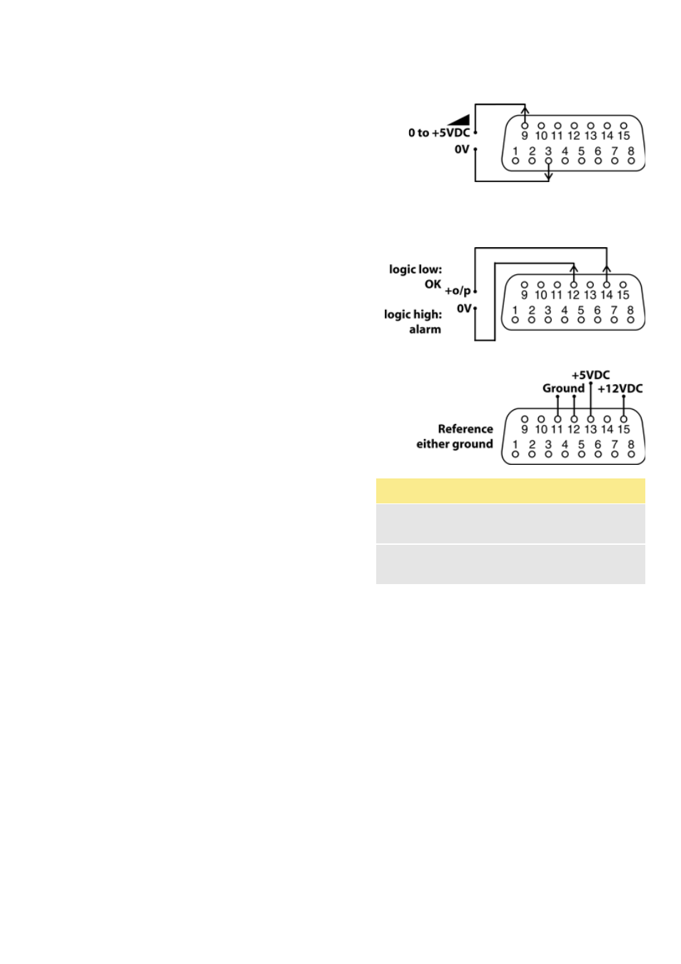
2.6.3 DC tacho output
For DC tacho output:
Connect external instrumentation: positive terminal
to pin 9; negative terminal to pin 3.
Note: This output is designed for low-resistance
equipment inputs of nominally 1k
Ω.
2.6.4 Digital alarm output
For digital alarm output (system errors only):
Connect an external TTL device: positive terminal to
pin 14; negative terminal to pin 12.
2.6.5 Supply voltages
+5VDC is available on pin 13. +12VDC is available
on pin 15. Tolerances better than 10%. Both sup-
plies are stabilised. Ground to pin 11 or pin 12.
DC
Voltage
Max
load
Pin
Typical use
+5V
10mA
13
Voltage supply for
inputs using remote
switch.
+12V
10mA
15
Possible voltage sup-
ply for inputs using
remote switch.