5 remote control wiring – Watson-Marlow 120U/D1 User Manual
Page 21
Watson-Marlow 120U IP31 pumps: operating instructions
7
2.5 Remote control
wiring
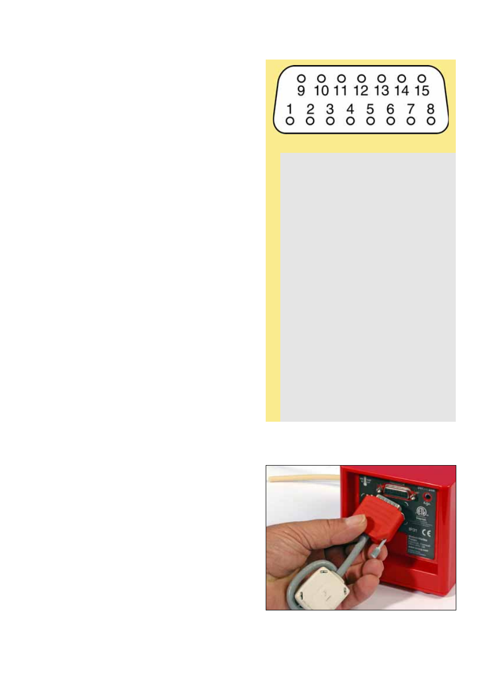
Interfacing the pump with other devices is by
means of a female 15-pin D-connector at the rear of
the pump.
A mating male connector, screened for EMC compat-
ibility, must be conventionally soldered to a
screened control cable.
Recommended control cable: 7 strands 0.2mm,
24AWG, screened, circular, up to 15-core.
The 15-way D-connector must be connected
before power is supplied to the pump. If any
change is made later to the 15-way D-connec-
tor, it must be re-connected before power is
supplied to the pump.
This pump passes all EMC compatibility require-
ments with up to 3m (10ft) of the cable type
specified above. Beyond this distance it is the user’s
responsibility to ensure the pump is safe and
reliable under remote and automatic control.
To minimise EMC interferance the wiring to the 15-
pin D-connector must be screened. The screen must
be earthed at the signal end of the wiring. To further
reduce EMC the screened wiring must be threaded
once or twice through a ferrite tubular cable shield
or a hinged clamp core.
The signal ground and DC supply ground lines on
this pump are isolated from ground by the external
DC supply unit. It can be connected to isolated 0V
or grounded 0V interfaces. The TTL (transistor
transistor logic) output is composed of two states:
nominally 0V and 5V; but in practice <0.4V
(<16mA) and 2.4-5V (<0.4mA). They are not
suitable for driving relays.
Pin
no
Input or output
Function
Referenced to
1
Digital input
Analogue Voltage
or Current Signal
Input Select
Connect to Digital
Ground for Current
2
Analogue input
Analogue Voltage
or Current Signal
Input (+)
Referenced to
Analogue Ground
3
Ground
Analogue Ground (0V)
4
Digital input
Remote Direction
Enable
Connect to Digital
Ground to enable
5
Digital input
Remote Direction
Connect to 5VDC
for counter-clock-
wise operation
7
Digital input
Manual or Auto
Mode Select
Connect to 5VDC
Supply for Auto
Mode
8
Digital input
Remote Start/Stop
Connect to 5VDC
Supply to stop
9
Analogue output
Analogue Tacho
Output
Referenced to
Analogue Ground
(0-5VDC signal)
10
Ground
Analogue Ground (0V)
11
Ground
Digital Ground (0V)
12
Ground
Digital Ground (0V)
13
DC supply
5VDC Supply (+)
Referenced to
Ground
14
Digital output
Alarm Output (5V
TTL)
Referenced to
Digital Ground
15
DC supply
12VDC Supply (+)
Referenced to
Ground
Note: The pin allocation of the 120U differs
from the pin allocation of the 101U and the
401U. See overleaf for details.