Using shelf rear panel functions, Connecting the signal and chassis ground, Using shelf rear panel functions -5 – Verilink Red Zone Encryption (REMS) (880-502423-001) Product Manual User Manual
Page 87: Connecting the signal and chassis ground -5, Connectors for the power supplies cables
Using shelf rear panel functions
Red Zone Encryption Management System (REMS) User Manual
9-5
Using shelf rear panel functions
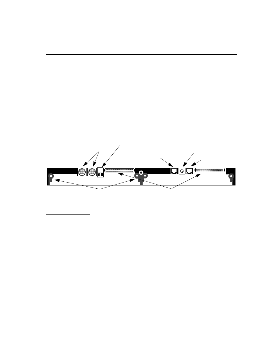
A shelf rear panel allows for rear connector modules to be installed and
secured. It also provides the following components:
■
connectors for the power supplies cables
■
connectors for ground connections and the expansion buses
■
shelf address switch
See Figur e9-3, Rear Panel View of Dual-line Shelf with Callouts.
Figure 9-3
Rear Panel View of Dual-line Shelf with Callouts
Connecting the
signal and chassis
ground
The signal and chassis ground connector (TB1) on the dual-line shelf
backplane connects the shelf to a proper grounding point. The signal and
chassis ground connector has two sockets:
■
The signal ground (SGND) conductor connects to the socket on the
left-hand side of the connector.
■
The chassis ground (CGND) conductor connects to the socket on the
right-hand side of the connector.
See Figur e9-4, Signal and Chassis Ground Connector on Rear Panel of
Dual-line Shelf.
C
B
A
9
8
7 6
5
4
3
2
1
0
FE
D
TB Signal and Chassis Ground Connectors
Shelf Address Switc
Dual Power Supply Connectors
Expansion bus connectors P3 and P4
J3
J4
Control Bus In
Control Bus Out
1 2
Mounting brackets for rear connector
module thumb screws