Diagnostics information, Diagnostics information -2 – Verilink QUAD DATA (880-503319-001) Product Manual User Manual
Page 36
Diagnostics
4-2
Verilink QUAD DATA User Manual
Diagnostics
Information
The first fifteen lines on the QUAD DATA Diagnostics Menu
present information about the status of each port. Arrows pointing
left or right appear next to the values for the control leads. These
indicate the origin of the referenced signals. A left arrow indicates
an input to the QUAD DATA module, a right arrow represents an
output from the QUAD DATA module.
details the information fields on the QUAD DATA
Diagnostics Menu.
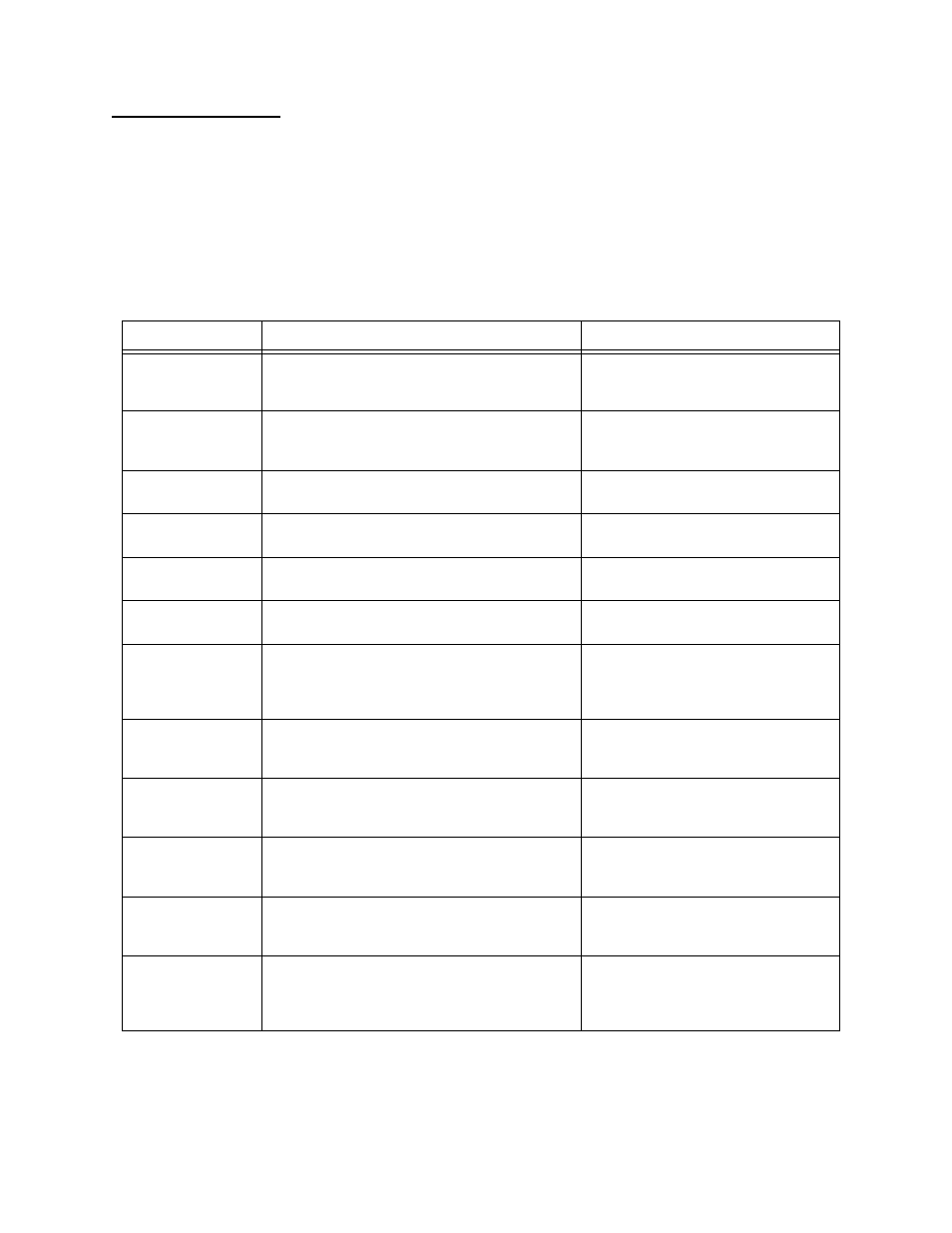
Table 4-1
Diagnostics Menu Information Fields
Display Field
Description
Instructions
Interface type
Indicates which synchronous serial interface
type has been selected for the port. Available
are V.35, X.21, RS-449, and EIA 530.
Use the QUAD DATA
Configuration Menu (
)
to change this selection.
DPL loopback
Indicates whether a Data Port Loopback is
currently in effect on the port. The Data Port
Loopback is a bi-directional loopback.
Use the
Dn)
command to establish
.
Far-end loopback
Indicates whether a far-end loopback,
initiated by this module, has been detected.
See the section “
in this chapter.
Test pattern
Indicates what test pattern, or none, is
running on the port.
Possible values are none or QRSS
(Quasi-Random Signal Sequence).
Pattern sync
During a test, indicates whether the receive
circuitry is in sync with the test pattern.
Used to verify the test pattern is
being received from the far end.
Test error counter
Cumulative indicator of bit errors received
during tests.
Use the En) command to reset the
test error counter. See
LOS detected
Loss Of Signal—Indicates whether the port
has detected the DTR lead, an output from
the DTE, is in a low (Off—negative voltage)
state.
Use the QUAD DATA
Configuration Menu (
)
to enable or disable LOS detection.
DTR (C)
Indicates the state of Data Terminal Ready (or
Control in the case of a port optioned for
X.21 interface type).
DTR is an output from the DTE and
an input to the QUAD DATA port
(when the port is in DCE mode).
DSR (I)
Indicates the state of Data Set Ready (or
Indication in the case of a port optioned for
X.21 interface type).
DSR is an output from the QUAD
DATA module in DCE mode. It is the
logical complement of DTR.
RTS
Indicates the state of Request To Send (not
applicable to X.21 ports).
RTS is an output from the DTE and
an input to the QUAD DATA port (in
DCE mode).
CTS
Indicates the state of Clear To Send (not
applicable to X.21 ports).
CTS is an output from the QUAD
DATA module in DCE mode. It is the
logical complement of RTS.
DCD
Indicates the state of Data Carrier Detect (not
applicable to X.21 ports). DCD will not be on
until the data port is mapped to an active
network port that is not in an alarm state.
DCD is an output from the QUAD
DATA module in DCE mode. It
indicates that the network port is not
in a red alarm condition.